 English
 русский
 Español
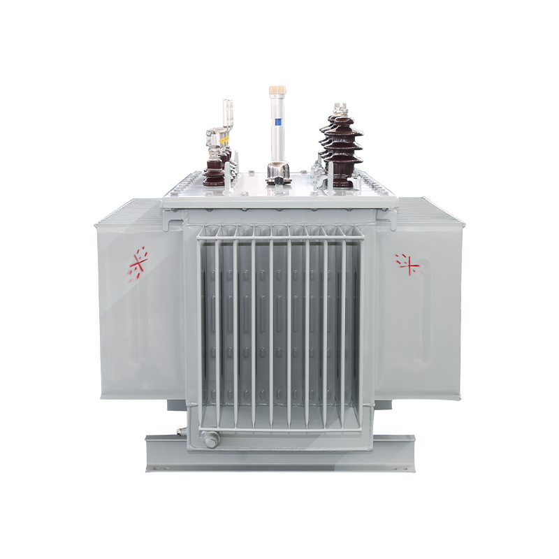
Energy-Saving Single-Phase Oil-Immersed Pole-Mounted Transformer
15KVA 13.8KV/0.4KV
See Details
Content
When most electrical professionals think of a transformer, they picture a passive, oil-filled or dry-type unit that steps voltage up or down at the grid frequency of 50 or 60 Hz. That picture is accurate for the vast majority of installations today. But a different class of device, the solid-state transformer (SST), has been under development for more than two decades, and it works on a fundamentally different principle. The short version is this: a solid-state transformer is a power-electronics-based AC-AC converter that uses high-frequency switching and a small high-frequency transformer to change voltage levels, rather than relying on a large, line-frequency magnetic core. It can do everything a conventional transformer does, plus several things a conventional transformer simply cannot. This guide explains what an SST is, how it is built, where it is genuinely useful, and why it has not yet replaced conventional equipment in most projects.
For readers who want a more condensed treatment of the same subject, we have published our earlier explainer on solid-state transformers as a companion piece to this deeper analysis.
A solid-state transformer is a power electronic converter that performs AC-to-AC voltage transformation using semiconductor switches and a high-frequency transformer. It is also known as a power electronic transformer (PET) or an electronic power transformer. The key distinction from a conventional transformer is the operating frequency. A traditional transformer operates directly at the line frequency of 50 or 60 Hz, which forces the magnetic core to be large and heavy. An SST first converts the incoming AC power to DC, then chops that DC into a high-frequency AC signal, typically in the kilohertz range. That high-frequency AC is fed through a physically small transformer, which provides voltage scaling and galvanic isolation. After the transformer, the power is converted back to the desired AC or DC output.
The research community has provided two widely cited definitions. Wikipedia defines an SST as a type of AC-to-AC converter, sometimes called a power electronic transformer or electronic power transformer. The FREEDM Systems Center at North Carolina State University, which has been a major hub for SST research, describes it as a collection of high-power semiconductor components, a conventional high-frequency transformer, and control circuitry. Both definitions converge on the same idea: an SST is a smart, actively controlled replacement for a passive magnetic component.
To make the difference concrete, consider the physical relationship between frequency and transformer size. The cross-sectional area of a transformer core is inversely proportional to operating frequency for a given voltage and flux density. A transformer running at 10 kHz can be dramatically smaller than one running at 60 Hz for the same power rating. The SST exploits this relationship to achieve significant reductions in volume and weight, which is one of its most frequently cited advantages.
The most fundamental change is that a conventional transformer is a passive device. It has no ability to regulate voltage, correct power factor, filter harmonics, or control power flow. It simply transfers energy according to the turns ratio of its windings, subject to the laws of electromagnetic induction. An SST, by contrast, is an active device. Its semiconductor switches can be controlled in real time, which gives it a set of capabilities that a conventional transformer cannot provide.
In short, the conventional transformer is a fixed, passive component, while the SST is a flexible, programmable power interface. This difference is not incremental; it changes what a distribution transformer can do for a grid or a facility.
The internal structure of an SST can be understood as a chain of power conversion stages. Semiconductor vendors, including Infineon, describe this as a "universal power electronic stack" concept, in which the same building blocks are combined to serve different power levels and applications. For a typical SST, the architecture consists of three main stages.
The first stage is the input rectifier. It converts the incoming AC line voltage into a DC bus voltage. This stage also provides power factor correction and can regulate the DC link voltage. The second stage is the isolated DC-DC converter. This is the heart of the SST. It switches the DC bus at high frequency, feeds the resulting AC through a high-frequency transformer for isolation and voltage scaling, and then rectifies it back to DC on the secondary side. The third stage is the output inverter. It converts the DC bus into the final AC output at the required voltage and frequency. If the application needs a DC output, this final stage can be omitted or simplified.
The high-frequency transformer inside the SST carries the full rated power of the device, but its magnetic core is a fraction of the size of a conventional transformer core. This is the core insight behind the SST: use high-frequency switching to shrink the magnetic component, and use semiconductors to handle the conversion work. The same logic applies to the related technology of power electronics in medium and high voltage systems, where converters and inverters face similar design trade-offs regarding switching frequency, thermal management, and harmonic performance.
There are two principal circuit topologies for solid-state transformers. The first is a pure AC-AC converter, which transforms voltage directly from one AC level to another without an intermediate DC link. This approach is simpler and may have a lower component count, but it lacks a DC bus, which limits its flexibility for integrating DC sources or storage.
The second topology is the AC-DC-DC-AC configuration, which is far more common in research and development. This design includes a rectifier stage, a DC-DC converter with a high-frequency transformer, and an inverter stage. The presence of a DC bus is a major advantage because it provides a natural point of connection for solar panels, batteries, or DC loads. Many research prototypes also employ modular multilevel converter structures, in which multiple submodules, each containing its own high-frequency transformer, are stacked to reach medium-voltage levels. This modular approach is well described in the academic literature on SSTs and is the dominant direction for high-power designs.
The potential benefits of SSTs are well documented in the research literature, particularly in the functional requirements outlined by the FREEDM Systems Center. These benefits are not merely theoretical; they map directly to real-world engineering problems in modern power systems.
Regarding efficiency, it is important to recognize that conversion losses are a key economic factor in any power system. For a deeper look at how losses translate into operational costs, our article on how transformer losses affect lifetime energy costs provides a useful framework.
Despite these benefits, the SST remains an emerging technology rather than a mature commercial product. As of 2025, after more than two decades of research and numerous prototype demonstrations, no significant commercial breakthrough has occurred. This is not for lack of effort or technical progress; rather, it reflects a set of persistent engineering and economic obstacles.
The first challenge is cost. Power semiconductor devices capable of operating at medium voltage levels are expensive, and the control systems required to manage them add further expense. The second challenge is reliability. A conventional transformer can operate for decades with minimal maintenance and has a well-understood failure profile. An SST contains dozens or hundreds of semiconductor switches, gate drivers, sensors, and cooling components, each of which is a potential failure point. Long-term field data on SST reliability under real grid conditions is still scarce.
The third challenge is engineering complexity. The high-frequency transformer must be carefully designed for efficiency and insulation, and the entire assembly requires sophisticated thermal management because power semiconductors generate significant heat. The fourth challenge is grid compatibility. The input stage of an SST is sensitive to voltage transients. As Wikipedia notes, an SST must be designed to withstand lightning and other surges, which is not a trivial requirement when semiconductor devices are involved. Surge protection, overvoltage coordination, and insulation coordination all need rethinking for a solid-state device.
In the current phase of the industry, these challenges mean that SSTs are not yet a drop-in replacement for conventional distribution transformers. For projects where proven, long-life equipment is required, the choice remains straightforward. Our analysis of total cost of ownership analysis for conventional transformers explains why lifecycle economics often favor tried-and-tested technology.
Even with these limitations, SSTs are being actively explored in several niche application areas where their unique capabilities justify the higher cost and complexity. These deployments are primarily demonstration projects and pilot installations rather than large-scale commercial rollouts.
Data centers are a prime candidate because they increasingly use DC distribution internally and are highly sensitive to volume and efficiency. An SST can eliminate multiple AC-DC conversion stages, improving efficiency and reducing floor space. Electric vehicle charging infrastructure is another strong candidate, especially for bidirectional charging (vehicle-to-grid, or V2G), which requires exactly the kind of bidirectional power flow that an SST provides. Renewable energy integration is a third area, as solar and wind systems benefit from the direct DC interface and the ability to manage variable power flows.
In the industrial sector, frequency converters for medium and high voltage drives share many of the same power electronics building blocks as SSTs. For these applications, however, the industry has a mature alternative: the phaseshifting rectifier transformers for MV drive systems that our company manufactures. These transformers are designed specifically to work with multi-pulse rectifiers, providing harmonic mitigation without the complexity of a fully solid-state system. They are a proven, reliable, and cost-effective solution for the industrial drive market.
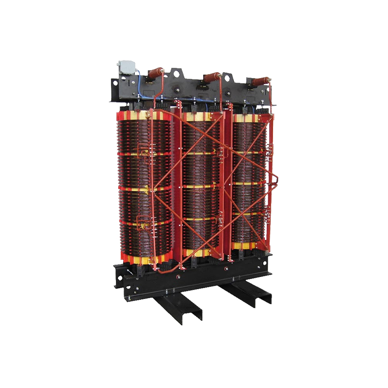
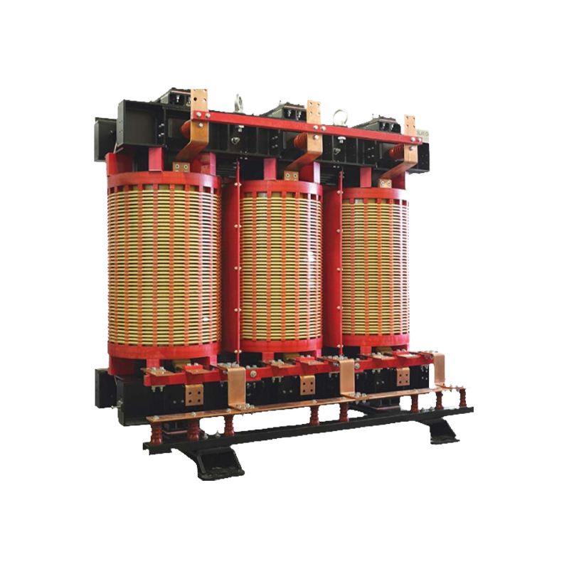 3000KVA Phase-Shifting Rectifier Transformer For Medium And High Voltage FrequenJiangsu Dingxin Electric is China OEM 3000KVA Phase-Shifting Rectifier Transformer For Medium And High Voltage Frequency Converters Manuf...View Product →
Similarly, for renewable energy projects that need a robust interface with the grid, dedicated transformer solutions remain the standard. Our technical article on transformers for wind solar and energy storage integration explains how these units are specifically engineered for the unique duty cycles of renewable generation.
For an engineer or project manager evaluating whether to deploy an SST, the decision should be based on a careful assessment of project requirements, not on technological novelty. The following framework is intended to guide that assessment.
First, consider whether you actually need the SST's unique features. The unavoidable advantages of an SST are its DC interface, bidirectional power flow, and fast dynamic control. If your project involves direct DC loads or sources, or if you need power to flow in both directions, an SST may be the only viable option. If your project is a conventional AC distribution feeder with unidirectional power flow, an SST offers little functional advantage over a conventional transformer.
Second, evaluate the reliability and maintenance implications. An SST is a complex electronic system that requires skilled maintenance and has a shorter expected lifespan than a conventional transformer. Are you prepared for the maintenance burden? Do you have personnel with the required power electronics expertise? In remote or harsh environments, this may be a decisive factor.
Third, compare total lifecycle costs, not just purchase price. The initial cost of an SST is significantly higher than that of a comparable conventional transformer. The economic case depends on whether the operational benefits, such as reduced losses, improved power quality, or eliminated conversion stages, can offset the higher capital expenditure over the project life. For most standard distribution applications, the math does not yet favor the SST.
Fourth, consider the maturity of the supply chain and standards. Conventional transformers benefit from well-established standards, a mature supply chain, and decades of operational data. SSTs are still in the early stages of standardization, and the supplier base is limited. This affects procurement risk, lead times, and long-term serviceability.
For the large majority of projects today, the honest engineering conclusion is that conventional transformers remain the optimal choice. This is especially true in space-constrained urban sites, where our compact energy-saving dry-type transformers for space-constrained sites provide a mature, reliable solution. The SST is an exciting technology, but it is not yet a general-purpose replacement.
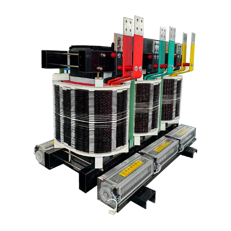 Insulated Energy-Saving And Environmentally Friendly Dry Type Transformer SuppliAs China Wholesale Insulated Energy-Saving And Environmentally Friendly Dry Type Transformer Suppliers and Custom Insulated Energy-Saving...View Product →
Solid-state transformers represent a genuine technological advance, offering capabilities that conventional transformers cannot match: bidirectional power flow, direct DC interfaces, active power quality management, and a dramatic reduction in size and weight. These features make SSTs a natural fit for the evolving landscape of distributed energy resources, electric vehicles, and DC data centers.
However, the technology is not yet mature enough for widespread commercial deployment. The challenges of semiconductor cost, long-term reliability, thermal management, and grid compatibility remain substantial. The coming years will likely see continued progress in power semiconductor technology, particularly in wide-bandgap devices such as silicon carbide, as well as more demonstration projects that build operational experience. These advances will gradually improve the economic and technical case for SSTs.
For the foreseeable future, conventional transformers will continue to be the backbone of the distribution grid. Project planners should watch SST development closely, but for immediate projects, the prudent choice is proven technology. As the grid evolves, it is worth tracking the broader trends in advancements in distribution transformer technology, which include both incremental improvements to conventional designs and the eventual commercialization of solid-state approaches.
At Jiangsu Dingxin Electric Co., Ltd., we bring this same engineering discipline to our current product line. While we do not manufacture solid-state transformers at this time, our work with phaseshifting rectifier transformers for MV drive systems reflects our experience in power electronics for demanding industrial applications. We are closely following SST development and will be well positioned to support our customers when the technology reaches commercial maturity. Until then, we focus on delivering the reliable, cost-effective transformers that keep power systems running today.
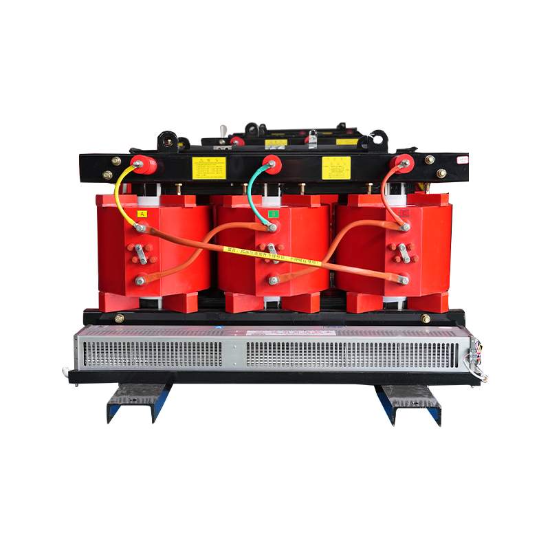
3000KVA Phase-Shifting Rectifier Transformer For Medium And High Voltage FrequenJiangsu Dingxin Electric is China OEM 3000KVA Phase-Shifting Rectifier Transformer For Medium And High Voltage Frequency Converters Manuf...View Product →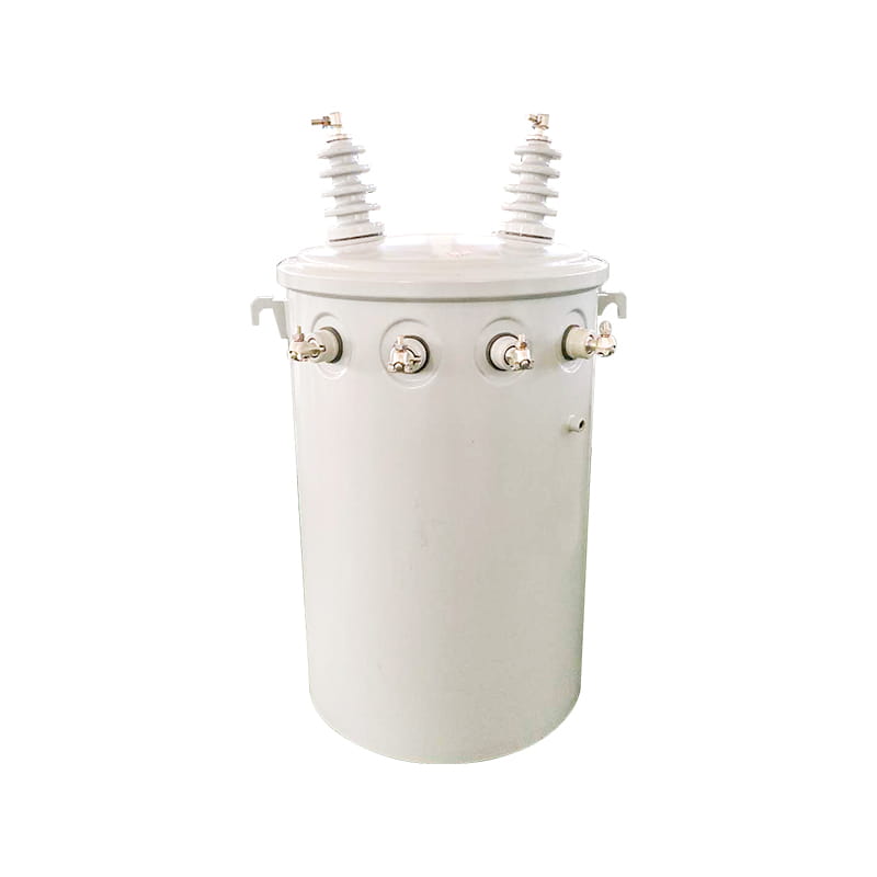
Copyright © Jiangsu Dingxin Electric Co., Ltd. Rights Reserved.

Energy Efficient Transformers Manufacturers Electrical Transformers Factory

Contact Us