 English
 русский
 Español
Energy-Saving Single-Phase Oil-Immersed Pole-Mounted Transformer
15KVA 13.8KV/0.4KV
See Details
Content
When a substation project fails to meet performance expectations, the root cause can almost always be traced back to decisions made before the first foundation was poured. The layout is too tight for safe maintenance, the transformer rating leaves no room for load growth, or the protection scheme is miscoordinated with downstream equipment. These are not construction problems; they are design problems, and they become exponentially more expensive to correct after energization. This guide walks through the complete design process — from defining functional requirements to selecting core equipment and preparing compliance documentation — with an emphasis on decisions that directly affect cost, footprint, and long-term operational reliability.
An electrical substation is a node in the power grid where voltage is transformed, current is routed, and protection is coordinated. It performs three functions that define its design: voltage transformation (stepping up for transmission or down for distribution), switching and routing (connecting or isolating circuits), and protection (clearing faults to protect upstream and downstream equipment). Every decision in the design phase ultimately serves these three functions, and every design flaw shows up as a failure in one of them.
Industry experience shows that design decisions lock in roughly 80% of a project's lifecycle cost. A transformer chosen with insufficient cooling capacity forces the operator to install external cooling later. A switchgear bay positioned without adequate withdrawal space makes breaker replacement a multi-day crane operation. An undersized grounding grid produces dangerous touch voltages during line-to-ground faults. Each of these examples traces back to a specification written too early or a layout approved without enough scrutiny. The design phase is where reliability is earned and where cost overruns are avoided.
Before any calculation begins, the project team must answer a fundamental question: what role does this substation play in the network? The answer determines voltage levels, breaker requirements, redundant paths, and even the physical form of the station. Three functional categories cover most projects.
Transmission substations operate at 110 kV and above, typically interconnecting high-voltage lines and feeding large load centers. They require robust protection schemes, redundant bus configurations, and generous equipment clearances due to higher system voltages. Distribution substations step down to 35 kV or below, serving local loads. They are more numerous, more compact, and often designed with simpler, more economical single-bus arrangements. Collector substations aggregate output from distributed generation — solar farms, wind parks, or battery storage — and step up to the transmission voltage. Their design is dominated by reverse-power flow considerations, reactive power management, and rapid load variability.
The classification matters because it drives engineering priorities. A transmission station prioritizes availability and fault tolerance; a collector station prioritizes power quality and flexibility; a distribution station prioritizes cost efficiency and operational simplicity.
The physical form is the second major branch of the design decision tree. Outdoor air-insulated substations (AIS) are the traditional choice: equipment is mounted on concrete pads, busbars are supported on lattice structures, and all live parts are exposed to the weather. They suit rural areas with ample land and moderate snowfall. Indoor gas-insulated substations (GIS) enclose all live parts in sulfur hexafluoride within a compact metal housing. They are appropriate for urban sites, coastal areas, and any location where land is costly or where salt spray would accelerate corrosion on exposed conductors.
Between these two extremes sits the prefabricated or skid-mounted substation. In this configuration, the transformer, switchgear, and auxiliary systems are factory-assembled into one or more weatherproof enclosures and delivered as a single transportable unit. For projects with strict schedule targets — renewable energy plant construction, emergency grid restoration, or temporary industrial supply — the prefabricated form reduces site work to foundation preparation, cable termination, and final testing. Site installation time typically drops from months to one or two weeks. The main design task becomes the selection of an enclosure with correct ingress protection, adequate internal ventilation, and sufficient space for cable routing and operator access.
Transformer capacity is the single largest cost driver in a substation, and it is the parameter that operational staff will live with for the equipment's 20- to 40-year lifespan. Undersizing produces overload trips and accelerated insulation aging; oversizing wastes capital and increases no-load losses. The design must balance these risks against a forecast of future demand.
The standard approach begins with a load inventory: list every connected load, classify it by type (residential, commercial, industrial, or generation), and apply appropriate demand factors. The coincident peak is calculated using the demand factor and diversity factor — the ratio of the system maximum demand to the sum of individual maximum demands. A typical utility planning criterion applies a 1.2 to 1.3 multiplier to the calculated load to account for future growth and operating contingencies. When the substation serves critical loads requiring N-1 security, the transformer capacity must be sufficient to carry the full downstream load with one unit out of service.
This planning horizon feeds directly into the physical layout. A station designed for one transformer with a pad margin for a second unit must allocate busbar space, cable trenches, and foundation area from day one. Retrofit expansion is always more expensive than planned expansion — the works are confined by the existing footprint, and outages are required to make new connections.
The single-line diagram is the foundational document of any substation design. It defines how many incoming and outgoing feeders exist, where transformers and breakers are connected, and how the protection zones are arranged. All subsequent engineering — relay settings, breaker ratings, busbar ampacity, physical layout — is derived from the SLD. Every design review should start by reading the single-line diagram, and no equipment purchase should be finalized until it is approved.
A typical SLD for a distribution-class substation contains the following elements: the incoming line (or cable) with a disconnector and circuit breaker, the step-down transformer with its OLTC (on-load tap changer) if specified, the outgoing busbar section, and multiple feeder circuits each with a breaker, current transformers, and a disconnector. Voltage transformers and surge arresters are connected either to the busbar or directly to cable terminations. The critical interaction is: the breaker performs fault interruption, the disconnector provides a visible air gap for maintenance, and the ground switch (where fitted) ensures that the isolated circuit is de-energized and bonded to earth before personnel approach.
When the SLD is being defined for a project, the first decision concerns the bus topology. A single-bus arrangement feeds all circuits from one common busbar. It is simple, cost-effective, and what most distribution substations use when the security of supply requirement is modest. A double-bus arrangement connects each circuit through a changeover disconnector to either of two busbars, allowing either bus to be taken out for maintenance, and is justified where load cannot be interrupted during busbar work. A ring bus or breaker-and-a-half configuration is reserved for high-voltage transmission stations where a single bus failure must not interrupt multiple feeders.
Transformer and switchgear selection is the stage where most purchase orders are actually written, and where the difference between a practical, maintainable station and a theoretical one is made. The parameters that matter at this stage are voltage rating, capacity, cooling class, tap-changer type, and loss level for the transformer; and rated voltage, short-circuit breaking current, and insulation medium for the switchgear.
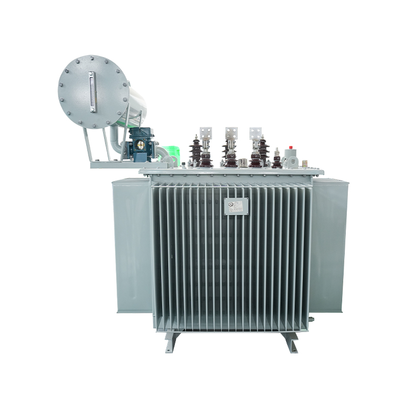
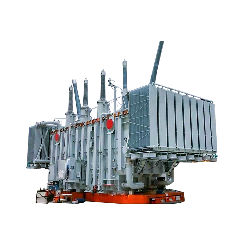
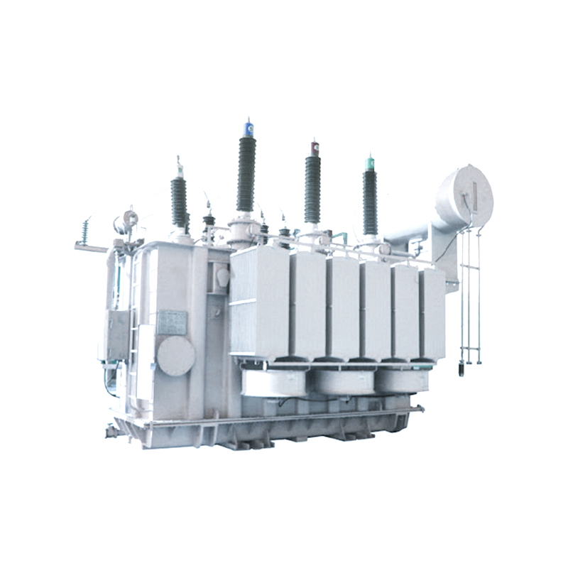
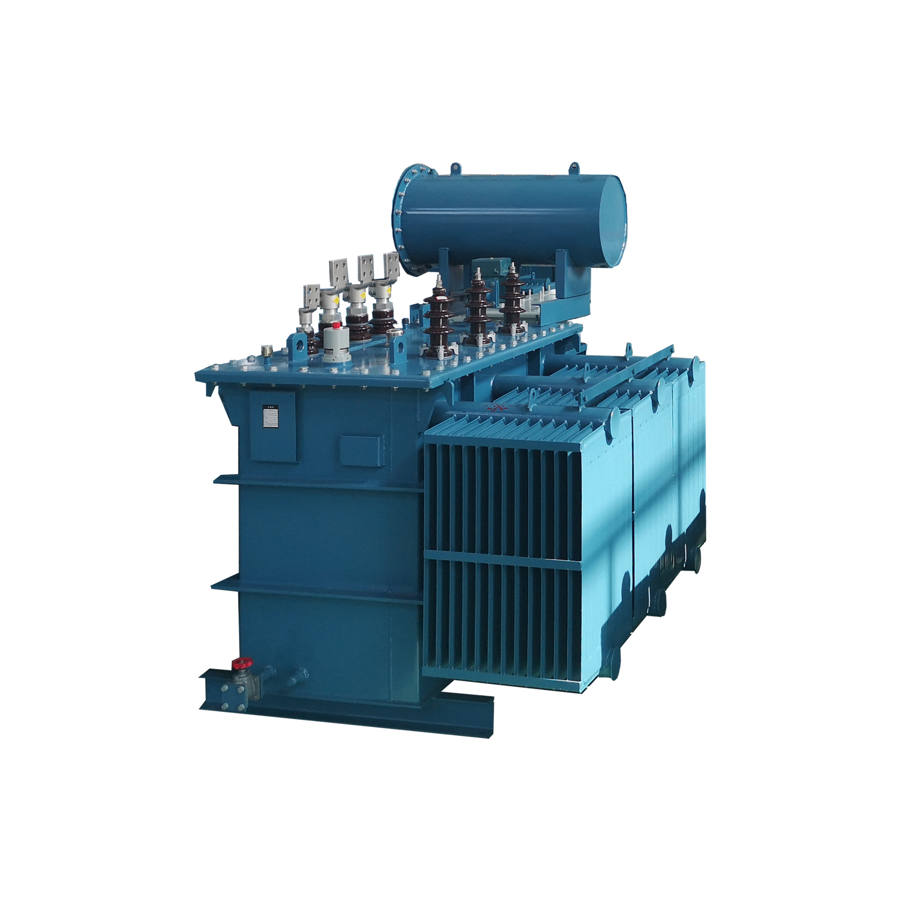
The insulation and cooling medium determines a transformer's enclosure requirements, fire resistance, and maintenance workload. Oil-immersed transformers use mineral oil for both dielectric insulation and heat dissipation. They have high overload capability, long established service records, and relatively low production cost. The trade-off is that the oil requires a containment system — a bunded pit or fire-rated wall — and the dielectric fluid presents a fire and pollution risk that must be managed for the installation's entire life. For outdoor sites with sufficient area for the oil containment and fire separation, oil-immersed units remain the standard choice for 35 kV and above. Readers reviewing typical utility choices may want to examine 35kV oil-immersed power transformer specifications to confirm how standard ratings align with distribution-class systems.
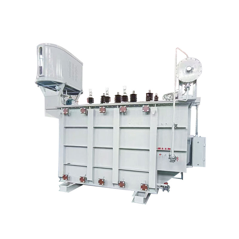 20000KVA 35KV Oil-Immersed Power Transformer Manufacturers, FactoryJiangsu Dingxin Electric is China OEM <p>20000KVA 35KV</p> 35kv Oil-Immersed Power Transformer Manufacturers and Factory, 35k...View Product →
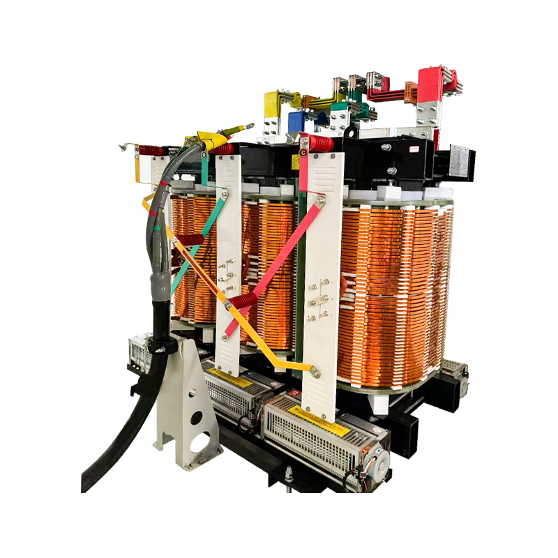
Dry-type transformers use either cast resin or Class H insulated windings with air cooling. They eliminate the fire risk, the oil containment requirement, and the monthly oil-quality sampling. For indoor installations — high-rise buildings, parking floors, tunnels, or any location where a pool of burning oil would be catastrophic — dry-type is effectively mandatory. The lifecycle operating cost is somewhat higher because dry-type units have higher no-load losses and lower overload capacity, but the reduced structural requirement often offsets the capital difference.
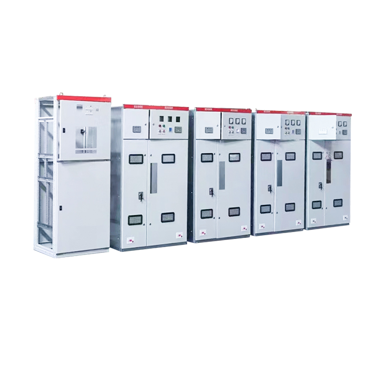
Core switching components have a strict functional hierarchy. The circuit breaker is the element that interrupts fault current — its rated short-circuit breaking capacity must exceed the maximum symmetrical fault current at the point of installation. The disconnecting switch, by contrast, is not intended to interrupt load or fault currents; it only isolates an already de-energized circuit to create a visible break. The busbar must be rated for either the maximum continuous current (for a distribution main bus) or for the emergency rating that results from an N-1 contingency. The coordination requirement is relatively simple but strict: the breaker clears faults, the disconnector supports the breaker's maintenance, and the busbar must withstand thermal and mechanical stresses during the breaker-cleared fault current, not just during normal operation. When assessing reliability class, specifying metal-enclosed high-voltage switch cabinets versus open-frame AIS arrangements is the focal decision point for indoor and compact installations.
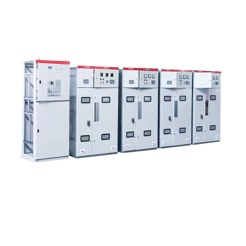 KYN28 Metal Enclosed High Voltage Switch Cabinet Manufacturers, Factory - JiangsJiangsu Dingxin Electric is China OEM KYN28 Metal Enclosed High Voltage Switch Cabinet Manufacturers and Factory, Metal Enclosed High Vol...View Product →
When site conditions bring constraints on land, installation time, or budget, the designer should seriously consider the prefabricated substation as the primary solution rather than a fallback. A conventional outdoor substation for a 35 kV distribution project requires site grading, equipment foundations, busbar structures, and a control room building — typically a construction period of six to nine months. A prefabricated substation integrates the transformer, medium-voltage switchgear, low-voltage switchgear, and auxiliary systems (meters, protection relays, heating, lighting, and communications) into a single factory-tested enclosure. Site work is limited to a prepared plinth, the installation of the enclosure, cabling between components, and a final commissioning test. The full installation can be completed in days.
For renewable energy projects, where the generation schedule is set by turbine or PV module delivery dates, the compact substation is often the critical path item. A factory-built unit removes civil works from the critical path entirely. For urban distribution, the compact footprint can reduce land acquisition costs by an order of magnitude. For industrial users needing temporary power during expansion, the compact unit can be relocated and reused. The designer should evaluate these alternatives side by side, comparing not only the first cost of the transformer and switchgear, but the cost of land, civil works, and the commercial cost of delayed energization. Those evaluating fully integrated solutions can review high- and low-voltage prefabricated substation options to assess which configurations match specific project constraints.
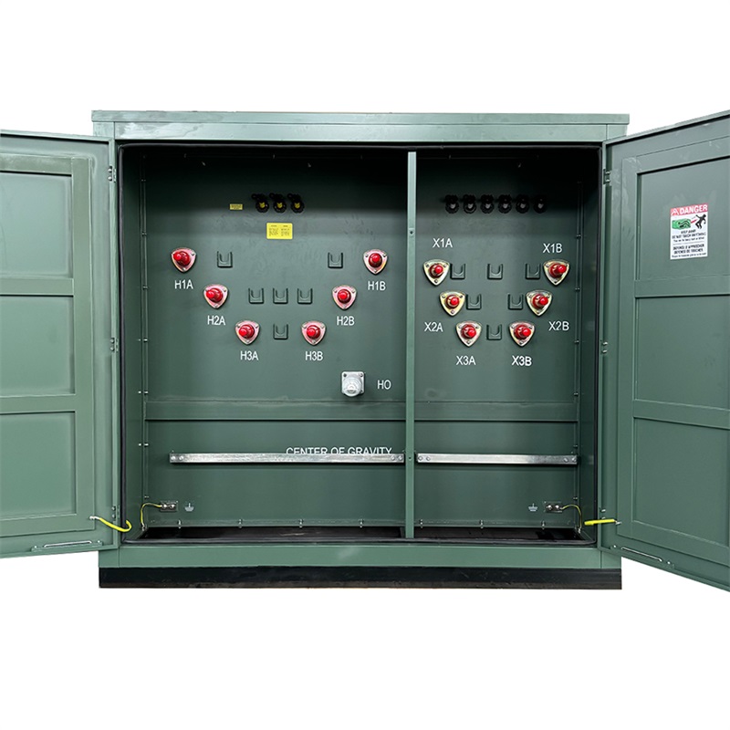
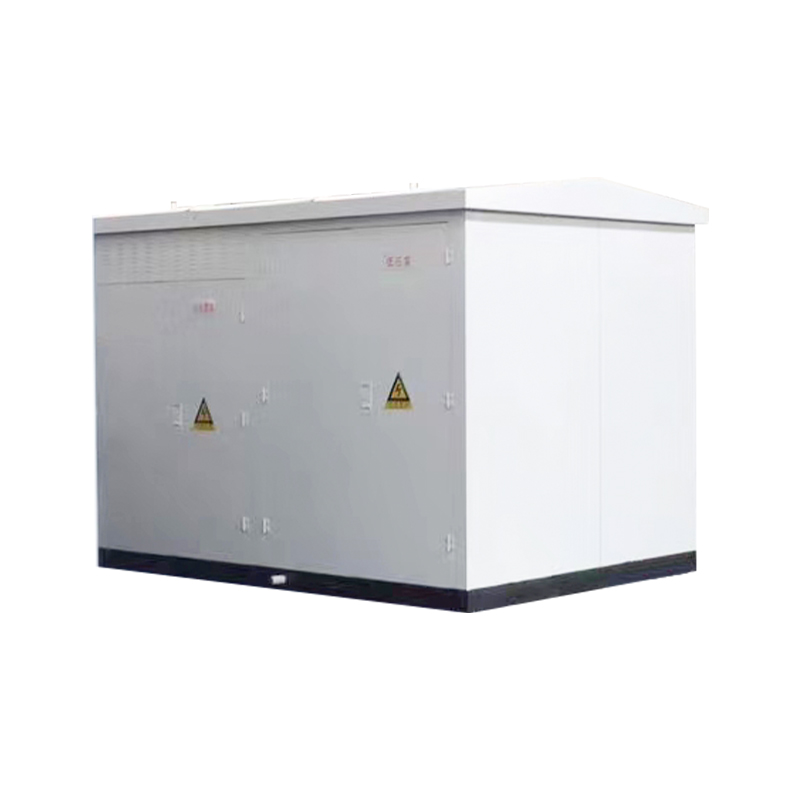 1600KVA 11KV 12KV 13.8KV High And Low Voltage Prefabricated Substation ManufactuJiangsu Dingxin Electric is China OEM 1600KVA 11KV 12KV 13.8KV High And Low Voltage Prefabricated Substation Manufacturers and Factory, H...View Product →
Layout and safety design transform a theoretical electrical system into a workable physical plant. The fundamental constraint is safety clearances: the minimum air distance between live parts of different phases, between live parts and grounded structures, and between live parts and accessible areas. These values are defined by IEC 61936 for installations exceeding 1 kV AC and by IEEE 1428 (among other standards) for specific aspects of high-voltage design; system designers should also reference IEC 60076 for transformer testing and installation limits. In the USA, the NEC/NESC framework applies to utility installations. The values are not optional — they define the physical envelope within which all equipment must be placed.
Grounding design is performed to limit step voltage and touch voltage to safe levels under line-to-ground fault conditions. The standard engineering reference is IEEE Std 80, which provides formulas for determining maximum allowable touch and step voltages based on fault duration and body resistance. The physical grounding system comprises a buried horizontal grid (typically bare copper conductors), vertical ground rods at grid intersections, and connections to every equipment frame and structure. The grid must be integrated with the substation's lightning protection system: surge arresters discharge transient energy to ground, and the ground grid provides a reference plane for the entire station. For a compact substation, the grounding design is relatively simple because the equipment is factory-bonded, but the enclosure must still be connected to the site's earth electrode system with a conductor sized to carry the full fault current.
Fire safety is a design driver rather than an afterthought. Oil-immersed transformers above a certain volume (typically 500 liters per compartment) require a fire barrier between the transformer and adjacent equipment. The thermal radiation from a transformer fire determines whether the station needs a dedicated fire suppression system (water spray or foam), whether the bund wall must be rated for fire resistance, and what minimum spacing is required between the transformer and switchgear or control rooms.
The protection system is the substation's nervous system; it senses abnormal conditions, isolates the faulted zone, and leaves the healthy network in service. The architecture is structured in three layers. The main protection operates with high speed (typically 20–40 milliseconds) and covers the primary asset — for a transformer, that is differential protection and Buchholz relay (for gas detection in oil); for a line, it is distance protection or pilot wire protection. The backup protection provides redundant fault clearing with a time delay if the main system fails. Breaker failure protection, the third level, trips adjacent breakers if the primary breaker fails to clear the fault within its designated time.
Supervisory control and data acquisition (SCADA) brings remote operation into the design. The substation must be equipped with RTUs or a bay controller that communicates with the dispatch center, transmitting the four key parameters: telemetry (measured values such as voltage, current, and power), tele-signaling (status of breakers and disconnectors), tele-command (remote operation of breakers), and tele-adjustment (setting changes on tap changers or relays). Modern monitoring adds condition data: oil temperature, winding temperature, dissolved gas analysis, partial discharge, and load profiles. The design must allocate space for these measurement devices and their communication interfaces from the outset, but the choice to display them on a local HMI or dashboard is a simple configuration decision.
Design work is not complete until the engineering is documented to a standard that can be reviewed, permitted, and constructed. The international framework is defined by three dominant standard systems. The IEC 60076 series governs transformer testing and performance; IEC 62271 governs high-voltage switchgear and controlgear; IEEE 80 (already referenced) covers grounding safety, IEEE 1428 and IEEE 665 support specific design aspects; and the Chinese GB standard series remains relevant for projects fabricated to that manufacturing base (for instance, GB 50059 covers substation design). Each standard does not replace the others; many export projects require compliance with IEEE in the US, with IEC in most other regions, and with the local grid code in the host country.
The output document set from a substation design contract is broadly similar across all industries. The deliverables are the single-line diagram (SLD), the general arrangement drawings (plan and section views), the layout of the grounding grid with the touch/step voltage calculation report, the protection coordination and relay-setting studies, the cable schedule and containment drawings, the bill of materials, and the technical specification for each major item. Without this bundle, the station cannot be constructed, tested, or accepted by the operator. Investing in these documents is what separates a repeatable design process from an improvised construction project.
Substation design is iterative, not linear. The load calculation influences the transformer specification, which affects the busbar ratings, which then drives the layout envelope — and any change to one parameter cascades through the others. The most useful design process keeps a closed feedback loop: equipment selection, physical layout, and protection coordination are reviewed as one integrated system, not as sequential tasks. For every design decision, a simple test applies: "Would I be comfortable operating this station in thirty years, with the original equipment, under a 20% higher load than predicted?" If the uncomfortable answer is "no," that soft spot in the design deserves more attention now — it will be much more expensive to address after commissioning. For designers looking for a complete walkthrough that parallels the steps here, our step-by-step substation design engineering guide provides a deepened discussion of each phase from a systems perspective.
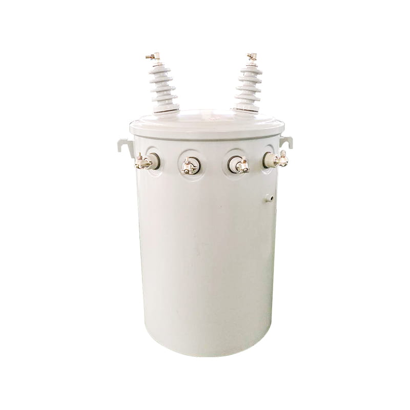

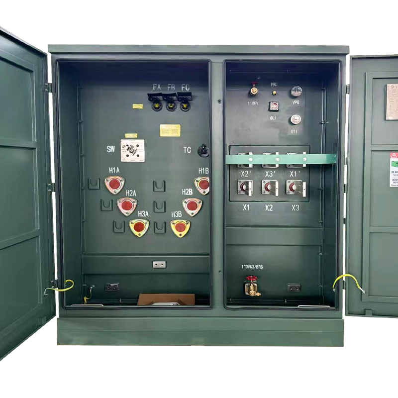
Base kVA: 45 kVA to 12,000 kVA Primary voltage: 2400 V to 46,000 V Secondary voltage: 120 V to 24,940V Basic lmpulse Level (BIL): 30kV to 250kV
See Details
Copyright © Jiangsu Dingxin Electric Co., Ltd. Rights Reserved.

Energy Efficient Transformers Manufacturers Electrical Transformers Factory
Contact Us