 English
 русский
 Español
50KVA Single-Phase Pole-Mounted Oil-Immersed Transformer
50KVA 34.5KV/0.48KV
See Details
Content
In 2022, a European utility pilot replaced a 1 MVA conventional distribution transformer with a solid state unit that weighed 40% less and cut no-load losses by half. That single swap crystallized what many power systems engineers already suspected: the century-old electromagnetic transformer now has a direct semiconductor challenger.
A solid state transformer (SST) — also called a power electronic transformer (PET) or electronic power transformer — is an AC-to-AC converter that replaces the heavy magnetic core and copper windings of a traditional transformer with power semiconductor switches, high-frequency magnetic isolation, and advanced digital control. Unlike a line-frequency transformer that simply scales voltage and current at 50 or 60 Hz, an SST actively shapes the voltage waveform in real time while maintaining galvanic isolation between input and output.
The defining hardware stack includes three functional stages: an input rectifier stage (AC/DC), an isolated high-frequency DC/DC converter stage, and an output inverter stage (DC/AC). All three are orchestrated by a central controller that adjusts switching patterns to regulate output voltage amplitude, frequency, and phase. SSTs typically operate at switching frequencies between 1 kHz and 50 kHz, shifting the isolation stage to a compact high-frequency transformer — often a ferrite or nanocrystalline core — rather than the bulky silicon-steel core of a 60 Hz unit.
The power flow through an SST can be visualized as three distinct conversion blocks, each with a specific role. The first block, the input stage, converts the incoming AC grid voltage to a regulated DC link voltage. In medium-voltage SSTs, this stage often uses cascaded H-bridge cells or modular multilevel converters to handle voltage stress across series-connected semiconductor modules.
The second block is the isolation stage. A DC/DC converter — typically a dual-active bridge (DAB) or a resonant LLC converter — drives a high-frequency transformer. Because the transformer only needs to handle a fraction of a cycle at kilohertz frequencies, its core cross-section shrinks dramatically. This stage provides the mandatory galvanic isolation between high-voltage and low-voltage sides while stepping the voltage up or down as needed. A 600 V DC link can be transformed to a 400 V DC bus with an isolation frequency of 20 kHz, using a magnetic core a tenth the size of an equivalent 60 Hz transformer.
The third block is the output stage, a DC/AC inverter that synthesizes a clean sinusoidal output voltage for the load. Advanced modulation techniques — such as space vector PWM or selective harmonic elimination — suppress unwanted harmonics and allow the SST to behave as an active filter. The controller also enables bidirectional power flow, voltage sag compensation, and seamless reconnection after faults. All three stages are monitored via DSP or FPGA controllers that execute protection algorithms and communication protocols like IEC 61850.
The gap between solid state and electromagnetic transformers is easiest to grasp when the two are placed on the same technical scorecard. The table below compares the most critical parameters, including efficiency, size, control capability, and upfront cost. Use it as a quick reference whenever a specification calls for faster voltage regulation or a drastic reduction in substation footprint.
| Parameter | Traditional Transformer | Solid State Transformer |
|---|---|---|
| Operating frequency | 50 / 60 Hz | 1 – 50 kHz (isolation stage) |
| Typical efficiency at rated load | 96 – 98% | 97 – 98.5% (SiC-based) |
| Volume and weight | Baseline (silicon steel core, copper windings) | 30 – 50% smaller and lighter |
| Voltage regulation range | ±2 – 5% (tap changers) | ±10% continuous, sub-cycle response |
| Harmonic mitigation | Passive filtering only | Active harmonic compensation, THD < 3% |
| Bidirectional power flow | No (passive device) | Yes, natively supported |
| Real-time monitoring / digital I/O | External CTs, RTUs required | Integrated sensing and grid communication |
| Initial capital cost (per kVA) | $15 – $25 | $45 – $75 (SiC modules) |
| Overload capability | 150 – 200% for minutes | 110 – 130% for seconds, limited by thermal management |
The capital cost delta remains steep, but the total cost of ownership gap is narrowing. Field data from a 2025 Silicon Valley microgrid project showed that when energy savings, avoided reactive power penalties, and reduced cooling loads were aggregated, the SST reached a payback parity of 3.5 years against a conventional oil-filled transformer. Still, reliability data beyond five years is scarce, and long-term semiconductor degradation in high-ripple environments remains an open question.
Solid state transformers unlock capabilities that no passive magnetic core can deliver. Four specific benefits are driving utility and industrial interest today.
Despite measurable performance gains, three hard barriers still keep SSTs confined to niche deployments and pilot projects.
No single topology dominates the SST landscape; the choice between cascaded H-bridge, modular multilevel, and dual-active bridge configurations depends on voltage class, power rating, and the desired control flexibility. The table below maps each topology to its sweet spot.
| Topology | Typical Voltage Range | Power Range | Peak Efficiency | Control Complexity | Best-Fit Application |
|---|---|---|---|---|---|
| Cascaded H-Bridge (CHB) | 2.3 – 13.8 kV | 100 kVA – 5 MVA | 97.5 – 98.5% | Moderate (cell balancing logic required) | MV distribution grid, rail traction |
| Modular Multilevel Converter (MMC) | 10 – 66 kV | 1 – 50 MVA | 98.0 – 99.0% | High (hundreds of submodules, circulating current control) | HVDC interfaces, large-scale renewables |
| Dual Active Bridge (DAB) | 400 V – 3.3 kV (DC link) | 10 – 500 kW | 97.0 – 98.0% | Low to moderate (phase shift modulation) | Data center UPS, EV fast charger isolation |
The CHB topology has proven especially popular in railway traction applications, where a 15 kV single-phase AC input can be split across multiple series-connected cells, each with its own low-voltage DC bus. MMC variants are advancing in offshore wind platforms, where 66 kV collector grids demand high reliability and inherent redundancy. The DAB, often combined with a front-end rectifier, forms the backbone of compact 30 kW EV charger modules that already achieve 98% peak efficiency in laboratory validation.
Solid state transformers are no longer confined to doctoral dissertations or government white papers. The deployment pipeline splits into three clear maturity tiers.
Across all three tiers, early adopters report that the most immediate operational return comes from eliminating separate reactive power compensation assets. One utility documented a 22% reduction in volt-ampere reactive (VAR) management hardware after retrofitting a feeder with an SST node, freeing up 15% of substation capacity for real power export.
Looking ahead, the SST trajectory will be shaped by two converging cost curves and one critical standards milestone. The U.S. Department of Energy’s 2026 power electronics roadmap projects that 15 kV SiC MOSFETs will cross the $1,500 per module threshold by 2028, cutting the bill-of-materials for a commodity 1 MVA SST by 35%. Concurrently, nanocrystalline core production is scaling in Asia, with unit costs falling 20% year-over-year since 2024.
The second force is standardization. IEEE Working Group P1709 is drafting a recommended practice for medium-voltage SST testing that will define power cycling profiles, accelerated humidity withstand tests, and electromagnetic compatibility limits. Once published — expected in 2027 — utilities will have a procurement-grade specification, accelerating the first volume orders for distribution-class SSTs.
The third force is integration. The next logical step fuses the SST with a solid-state DC breaker on a single ceramic substrate, creating a true "digital substation" cell. When that cell reaches a mean time between failure of 100,000 hours under realistic load profiles, the cost-benefit calculus will shift decisively. Until then, the smartest grid planning strategy pairs SSTs in applications where power quality and DC access justify the premium, while leaving the bulk of long-proven, low-cost electromagnetic transformers in place. For facilities weighing that trade-off, a traditional power transformer remains the most bankable baseline, and bridging technologies like a phase-shifting rectifier transformer already deliver harmonic mitigation and DC compatibility without the full semiconductor price tag.
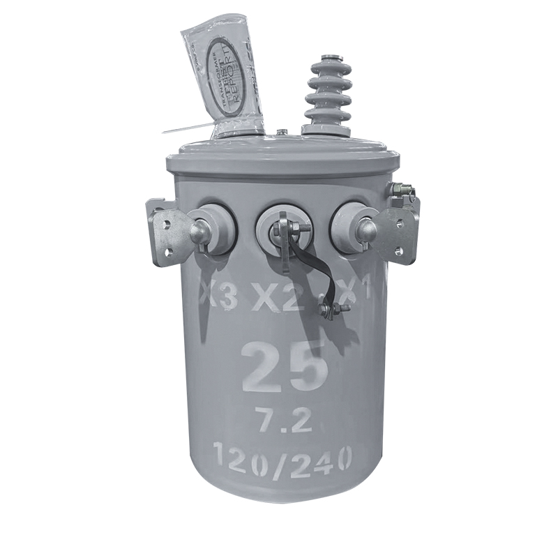
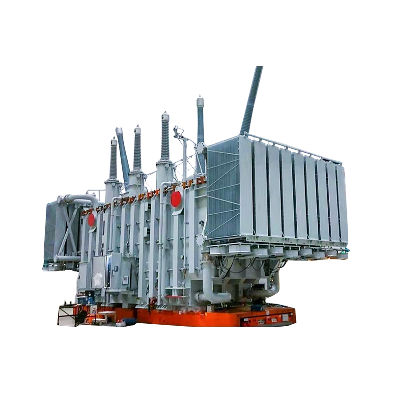
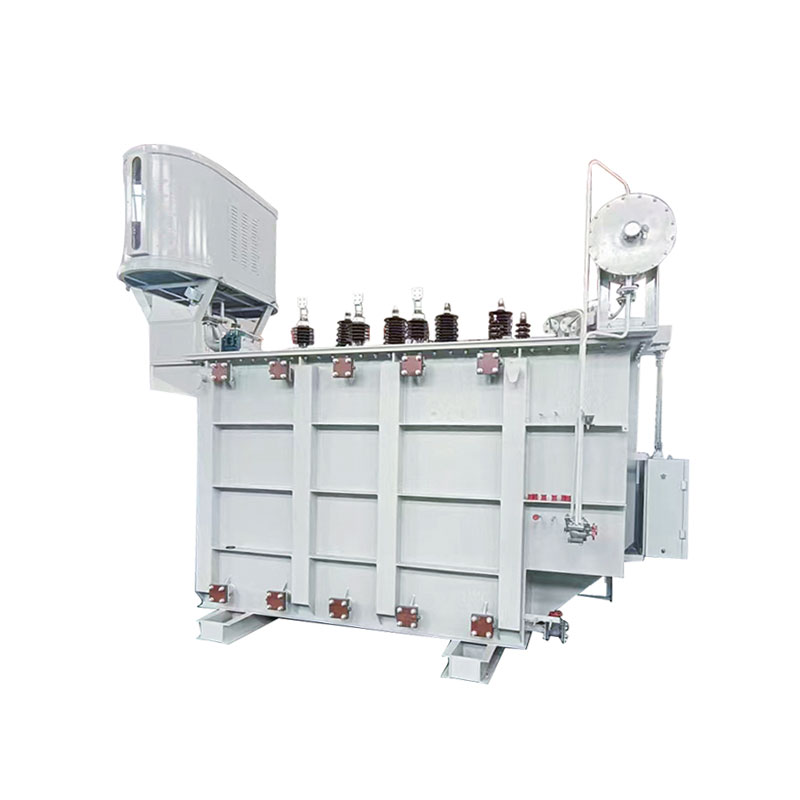
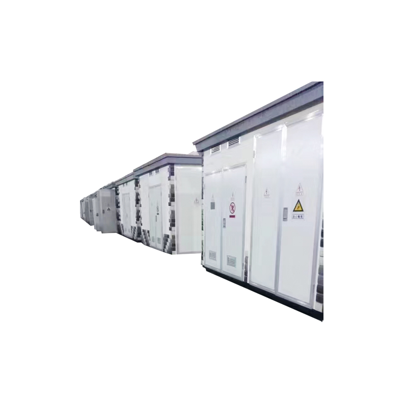
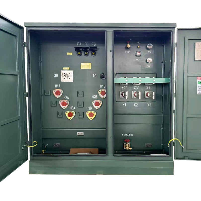
Base kVA: 45 kVA to 12,000 kVA Primary voltage: 2400 V to 46,000 V Secondary voltage: 120 V to 24,940V Basic lmpulse Level (BIL): 30kV to 250kV
See Details
Copyright © Jiangsu Dingxin Electric Co., Ltd. Rights Reserved.

Energy Efficient Transformers Manufacturers Electrical Transformers Factory
Contact Us