 English
 русский
 Español
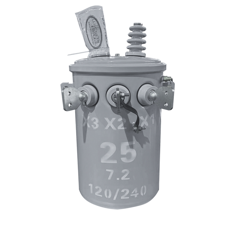
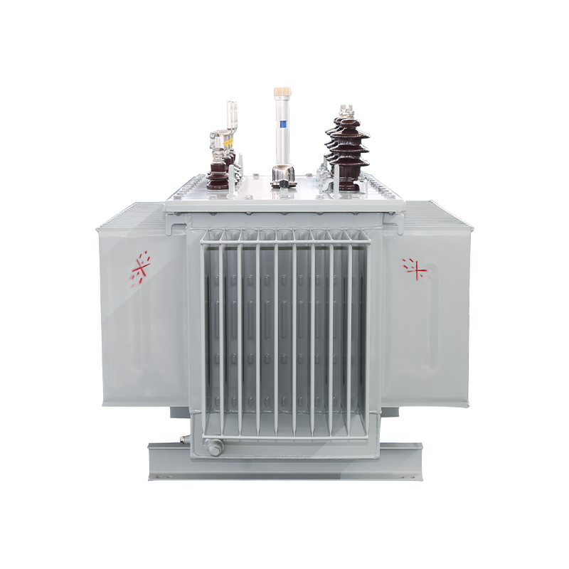
50KVA Single-Phase Pole-Mounted Oil-Immersed Transformer
50KVA 34.5KV/0.48KV
See Details
Content
Consider this scenario: a 110kV power transformer has just completed a 600-kilometer overland journey to a substation site. The routine oil tests and winding resistance measurements all pass, yet hidden mechanical damage from vibration or an unexpected shock during transit may already be compromising the core and windings. Standard electrical tests will not reliably reveal this damage. That is precisely where Sweep Frequency Response Analysis (SFRA testing) becomes indispensable.
SFRA testing works by injecting a low-voltage sweep frequency signal into a transformer winding across a broad frequency spectrum—typically from 10Hz up to 2MHz. The test records the winding's transfer function, creating a unique frequency response "fingerprint." Because the physical geometry of windings determines their distributed capacitance and inductance, any mechanical displacement—whether axial or radial winding deformation, core movement, or coil collapse—alters this LCR network and shifts the frequency response curve.
The critical difference between SFRA and conventional tests lies in what each method detects. Winding resistance, turns ratio, and excitation current tests evaluate electrical continuity and insulation condition. SFRA testing is specifically designed for mechanical integrity—a dimension these routine tests cannot see. For utility engineers, asset managers, and project procurement teams, this makes SFRA the definitive tool for verifying that a transformer's active parts remain physically intact.
Understanding what each frequency band reveals is central to interpreting SFRA results. A full sweep captures the transformer's response across four distinct zones, each sensitive to different physical characteristics:
This frequency segmentation is not arbitrary; it directly correlates with the physical scale of the defect relative to the wavelength of the test signal. Practically, this means a low-frequency change points to core-level issues, while a high-frequency change points to winding-level structural problems.
Once you have a frequency response curve, the next challenge is determining whether the transformer is healthy. SFRA interpretation relies on three established comparison methods, each with distinct strengths:
A practical decision framework uses phase comparison as the initial screening step, then confirms any suspected anomalies through time-based comparison against the factory baseline. When a baseline is unavailable, treat the current measurement as the new reference and establish a documented time-based record for future tests.
Executing a reliable SFRA test demands more care than connecting a test set and pressing "start." Following a disciplined procedure ensures repeatable results that you can trust for years of comparative analysis.
Confirm the transformer is fully de-energized, isolated, and properly grounded. Discharge any residual charge completely. Record the nameplate details, including connection group, voltage class, and most importantly, the tap changer position. The tap position changes the number of active turns and therefore alters the frequency response—inconsistent tap positions are a leading cause of misleading SFRA comparisons.
Two standard configurations are used: an open-circuit test (the non-tested windings remain open) and a short-circuit test (the non-tested windings are shorted). Both configurations are typically applied to cover all winding combinations. Each phase must be tested under identical conditions to ensure valid phase-to-phase comparisons.
Run the sweep from low to high frequency, recording curves for each winding pair. Document the test date, ambient temperature, humidity, equipment model, calibration status, and lead lengths. If possible, photograph the lead arrangement; this documentation is invaluable when reproducing identical conditions for the next test, particularly for the ultra-high-frequency range where parasitic capacitance is sensitive to lead path.
SFRA is notoriously sensitive to test setup. A slight change in the ground connection or lead routing can create meaningful shifts in the high-frequency region. Standardize the connection procedure and use the same cables, grounding points, and test sequence for every subsequent test on the same transformer.
When a response curve deviates from the reference, work through a systematic frequency-by-frequency diagnostic process rather than jumping to conclusions. The following framework guides you through the interpretation:
For readers who want to go deeper into curve-by-curve analysis, our step-by-step SFRA result interpretation guide provides a detailed walkthrough of real-world curve patterns and their diagnostic significance.
From the factory floor to end-of-life assessment, specific lifecycle milestones demand SFRA testing. Missing any of these windows creates gaps in the mechanical integrity record that are difficult to fill retroactively.
The baseline SFRA measurement must be performed at the factory before shipment. This is the single most valuable reference point for all future comparisons and aligns with the industry principle that SFRA is "the last test before departure." For larger units like the 110kV ultra-high-voltage power transformer, the factory baseline establishes the mechanical signature against which all transport and installation damage is assessed.
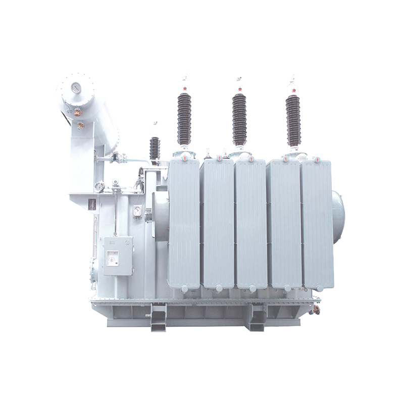 5MVA 110KV Ultra-High Voltage Power Transformer Manufacturers, FactoryJiangsu Dingxin Electric is China OEM 5MVA 110KV 110kv Ultra-High Voltage Power Transformer Manufacturers and Factory, 110kv Ultra-High V...View Product →
Immediately after delivery—before commissioning—conduct the first post-transport SFRA and compare it directly with the factory baseline. This step is especially critical for cross-border shipments involving sea freight or long-distance road transport. Install the unit, then perform a second confirmation test after installation is complete to exclude any movement introduced during final positioning.
Any nearby short-circuit fault, even one cleared quickly by protection relays, generates enormous electromechanical forces that can displace windings. Run an SFRA test as soon as possible after such an event, regardless of whether conventional tests indicate normal operation.
For mid-voltage distribution assets such as a 35kV oil-immersed power transformer, schedule SFRA testing every 3 to 5 years as part of a comprehensive condition assessment. Shorten the interval if previous tests showed anomalies or if the unit operates under severe loading or harsh environmental conditions.
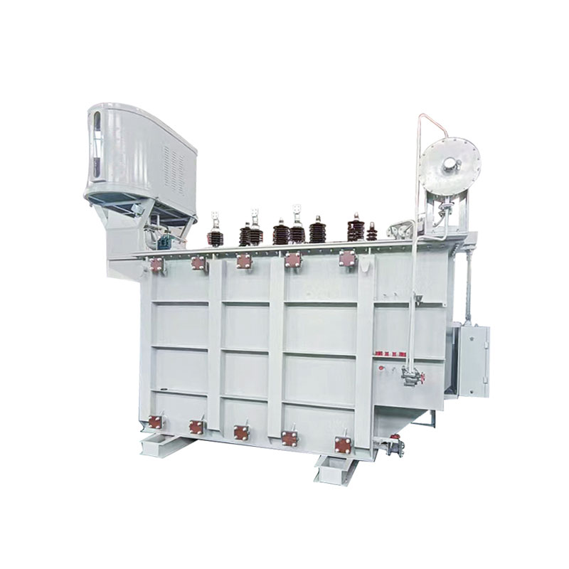 20000KVA 35KV Oil-Immersed Power Transformer Manufacturers, FactoryJiangsu Dingxin Electric is China OEM <p>20000KVA 35KV</p> 35kv Oil-Immersed Power Transformer Manufacturers and Factory, 35k...View Product →
Additional triggers include long-term outages, seismic events, or flooding—any situation where mechanical stress on the transformer structure is plausible.
SFRA testing does not replace conventional diagnostic methods; it complements them by covering a dimension they cannot see. The table below summarizes the role of each test in a complete diagnostic program:
| Test Method | Primary Detection Capability | Limitation Addressed by SFRA |
|---|---|---|
| Winding resistance | Loose connections, open turns | Cannot detect mechanical deformation without electrical failure |
| Turns ratio test | Turn count errors, major shorted turns | Insensitive to radial or axial winding displacement |
| Excitation current | Core condition, magnetic circuit anomalies | Cannot localize mechanical distortion |
| DGA (Dissolved Gas Analysis) | Thermal faults, partial discharge activity | Cannot detect purely mechanical damage without thermal signature |
| SFRA | Mechanical integrity: winding deformation, core movement | Does not directly assess insulation quality or oil condition |
The most effective asset management strategy combines SFRA with routine electrical tests and DGA to create a three-tier coverage—electrical, insulation, and mechanical. When SFRA reveals a structural anomaly, the complementary tests help determine whether the damage has progressed to electrical or thermal consequences.
Even experienced engineers can undermine the value of SFRA testing through avoidable procedural errors. The following pitfalls account for most unreliable or uninterpretable test results:
From a transformer manufacturer's perspective, no test better protects the buyer's investment than a properly executed SFRA program—starting with a trustworthy factory baseline and continuing through disciplined lifecycle testing. When the mechanical integrity record is consistently maintained, you gain the confidence to make informed decisions about repairs, continued operation, or replacement, ultimately extending the reliable service life of critical power assets.
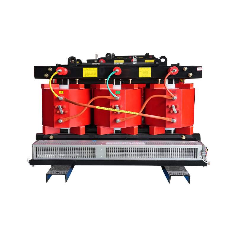
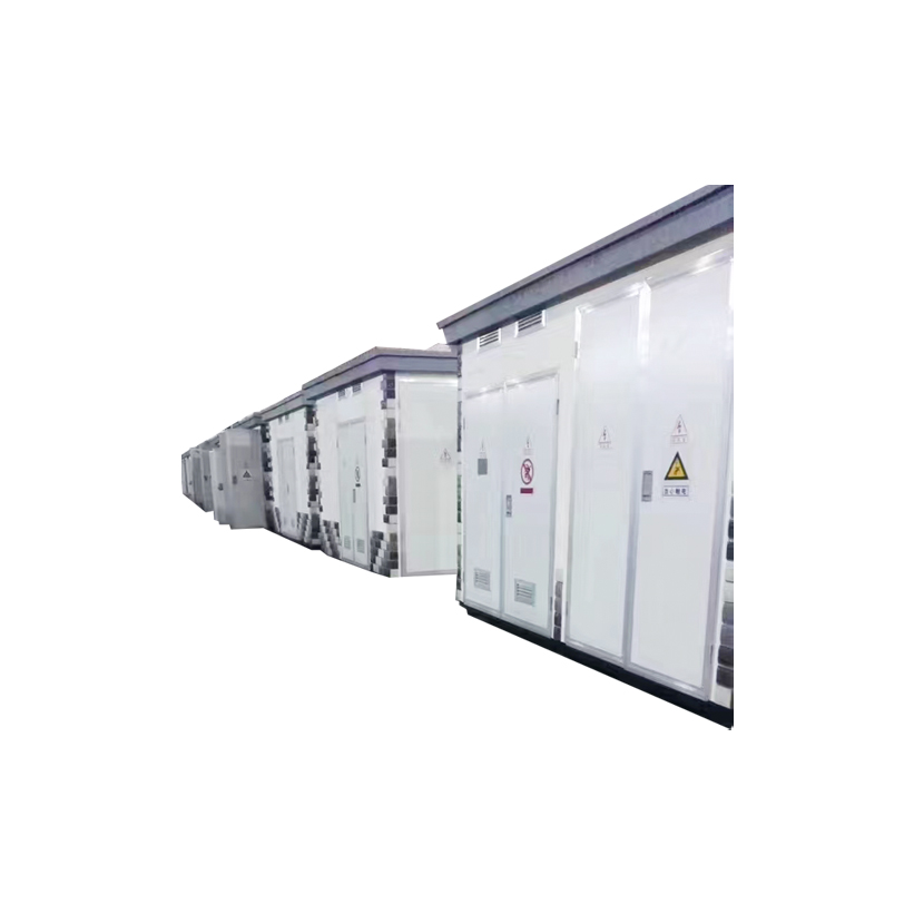
A Cabinet-Type Outdoor Prefabricated Substation, which is a compact, all-in-one electrical distribution solution designed for outdoor installation. Th...
See Details
Copyright © Jiangsu Dingxin Electric Co., Ltd. Rights Reserved.

Energy Efficient Transformers Manufacturers Electrical Transformers Factory
Contact Us