 English
 русский
 Español
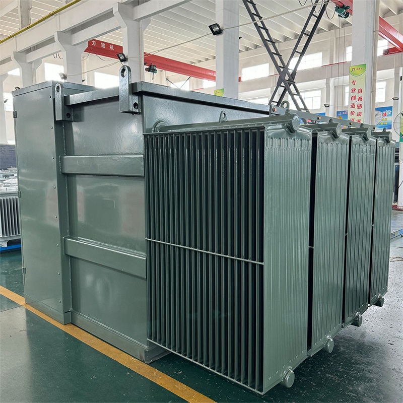
Energy-Saving Single-Phase Oil-Immersed Pole-Mounted Transformer
15KVA 13.8KV/0.4KV
See Details
Content
Shell-type cores are built from stacked laminated steel plates that form two outer limbs and a central limb; the windings are placed on the central limb. Lamination grade, stacking factor, and insulation varnish selection directly influence core losses and inrush current. Designers optimize lamination thickness (commonly 0.35–0.50 mm for distribution classes) to balance eddy-current loss and mechanical rigidity.
Primary and secondary windings in shell-type transformers are concentric or coaxial on the central limb and often separated by layers of solid insulation and interleaving (especially in high-voltage units). Insulation material choices (pressboard, Nomex, epoxy) and phase-to-phase spacing are selected according to voltage class, altitude derating, and impulse withstand requirements.
Because the core surrounds the windings, shell-type transformers offer inherently robust mechanical support. This reduces winding movement under short-circuit forces. When designing or selecting a unit, confirm that clamping structures, bracing, and anchoring points meet the seismic or transport vibration standards relevant to the installation site.
| Parameter | Shell-Type | Core-Type |
| Winding Support | Windings enclosed by core — higher mechanical support | Windings on limbs — exposed to lateral forces |
| Leakage Flux | Lower leakage inductance — tighter coupling | Higher leakage — can be advantageous in fault isolation |
| Cooling | Core surrounds windings — cooling channels must be designed carefully | More open geometry — often easier oil circulation |
| Application Fit | Compact installations, noise-sensitive, high mechanical stress | General distribution, higher power transmission units |
Mount the transformer on a rigid foundation to prevent core or winding deformation. Use vibration-isolating pads if required, but ensure anchoring prevents lateral movement under short-circuit forces. Check alignments for bus duct and cable entries to avoid mechanical stress on terminals.
Proper earthing of the core and shielding reduces circulating currents and prevents hum-related faults. If the shell design uses electrostatic shields between windings, verify the shield termination per manufacturer guidelines to avoid unintended ground loops.
Shell-type layouts require deliberate cooling channel design because the core encloses windings. For oil-immersed shell transformers consider natural (ONAN) vs forced oil/air (ONAF) cooling, radiator sizing, and oil circulation paths. For dry-type shell transformers, ensure sufficient air clearance and consider forced-air cooling fans when continuous overloads are expected.
Mandatory protection includes differential protection, overcurrent relays, Buchholz relay (for oil-filled units), pressure relief devices, and temperature sensors (RTDs or thermistors). For critical applications add dissolved gas analysis (DGA) connections and partial discharge monitoring for early fault detection.
Perform insulation resistance (Megger), winding resistance, turn ratio (TTR), no-load and short-circuit tests, and polarity checks. For oil-filled shell transformers include oil dielectric strength (BDV) and moisture content. Document baseline values for future comparisons.
Noise levels depend on core clamping, lamination quality, and loading; shell-type designs can be quieter in some configurations because magnetic flux is more contained, but proper mechanical assembly is critical.
Choose cast-resin shell transformers when oil hazards are unacceptable (indoor installations, substations near public buildings), or when low-maintenance, fire-resistant units are required. Ensure humidity and dust controls because cast-resin units are sensitive to conductive contamination.
Typical documentation includes nameplate and rating details, wiring and terminal diagrams, factory test reports (TTR, impulse, open-circuit/short-circuit), oil/gas analysis certificates if applicable, maintenance manual, and spare parts list.


Copyright © Jiangsu Dingxin Electric Co., Ltd. Rights Reserved.

Energy Efficient Transformers Manufacturers Electrical Transformers Factory


Contact Us