 English
 русский
 Español
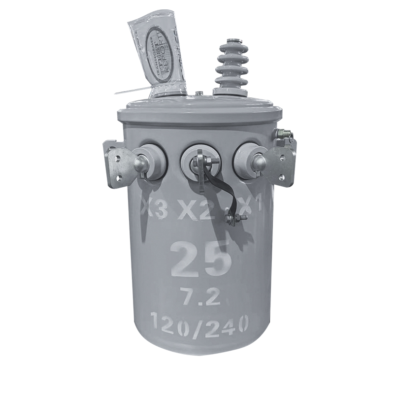
50KVA Single-Phase Pole-Mounted Oil-Immersed Transformer
50KVA 34.5KV/0.48KV
See Details
Content
Partial discharge rarely announces itself with a bang. It begins as a microscopic electrical breakdown inside the insulation, a spark that lasts nanoseconds and repeats thousands of times a minute, quietly carbonising paper, resin or oil until the insulation can no longer hold voltage. A partial discharge test on a transformer is the practical way to catch that process early, either in the factory before the unit ships or on site long before it fails.
This guide walks through what partial discharge really is, the main ways to measure it, what factory testing and on-site testing each give you, and how to read the results without overreacting to a single number. It is written for the engineers, project managers and procurement teams who have to sign off on a transformer and live with the consequences.
Partial discharge is a localised dielectric breakdown that does not bridge the full insulation distance between two electrodes. The textbook case is a gas-filled void trapped inside cast resin, or a bubble suspended in transformer oil. Gas has a lower permittivity than the solid or liquid around it, so the electric field concentrates inside that small cavity. Once the local stress exceeds the breakdown strength of the gas, it ionises, discharges, and then recovers, only to discharge again on the next half cycle.
Each event transfers a very small amount of charge, which is quantified as an apparent charge and expressed in picocoulombs (pC). Nothing about the unit looks wrong from the outside. That is precisely why the test matters: it detects a degradation mechanism years before a fault current or a gas alarm would.
When engineers talk about a partial discharge test on transformer insulation, they are usually asking three separate questions. Does discharge exist above a defined threshold? At what voltage does it start and stop, which we call inception and extinction? And where inside the winding, core or bushing is the charge coming from?
There is no single instrument that answers every question. Most test programmes combine two or more techniques, because each one trades sensitivity against noise immunity and location accuracy.
| Method | What it senses | Typical application | Practical notes |
|---|---|---|---|
| Conventional electrical (IEC 60270) | Apparent charge in pC | Factory routine and type tests | Best sensitivity in a shielded test bay; requires calibrated charge injection |
| UHF detection | Electromagnetic waves in the GHz range | On-line monitoring of power transformers and GIS | Strong noise immunity; results are comparative rather than in pC |
| Acoustic emission | Ultrasonic pressure waves | Locating the defect inside a tank or winding | Excellent for localisation, weak for quantifying severity |
| HFCT and TEV sensors | High frequency current and voltage pulses | Portable surveys on cables, switchgear and transformers | Fast to deploy; best used as a screening and trending tool |
| Dissolved gas analysis | Hydrogen, methane, acetylene in oil | Oil-immersed units in service | Confirms that discharge or overheating is active, not a PD measurement itself |
For a new power transformer, the reference measurement is an induced voltage test with simultaneous discharge measurement, carried out in a shielded bay with a calibrated measuring system. The voltage is raised to a pre-stress level to condition the insulation, held for a defined period, then reduced to the measurement level where readings are taken. The exact profile, and the limit that applies, follow the standard your project specifies and the purchaser's technical specification.
As a rough orientation, declared limits in the industry commonly start around 100 pC at 72.5 kV voltage class and step up to 200 pC or more as the voltage class rises. A limit is only meaningful together with the voltage at which it is measured, so always read the two together.
The routine test proves that this particular unit has no harmful discharge at the specified level. Type tests, such as a long-duration AC induced voltage test with discharge measurement or an impulse test with discharge recording, are performed once on a design to demonstrate that the insulation system itself is sound. Together they tell you whether the design is good and whether the manufacturing process delivered it consistently.
In practice, factory testing is where casting voids, dry spots in oil-impregnated paper, sharp electrode edges and incomplete impregnation show up. Finding them here costs a rework. Finding them on site costs a shutdown.
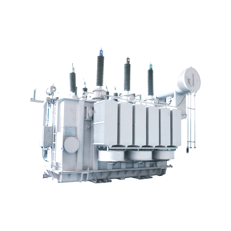
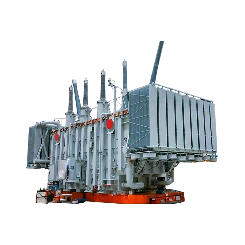 100MVA 220kV Low Loss Power TransformerThis 100MVA 220kV transformer supports transmission and distribution voltage stepping with overcurrent, overtemperature, and pressure-relief protection; relevant to factory and on-site discharge testing discussions.View Product →
Once a transformer is installed, the situation changes. There is no shielded test bay, the background noise level is unpredictable, and the unit is often connected to a live network. On-site discharge testing is normally done for one of four reasons: commissioning after transport and reassembly, verification after a repair or oil treatment, a periodic condition survey, and continuous on-line monitoring of critical assets.
A sensible on-site procedure looks like this:
Repeatability matters more than absolute accuracy here. Two surveys taken with the same setup and compared against each other are far more useful than one survey interpreted in isolation.
In oil-filled units, discharge typically originates from gas bubbles, free moisture, metallic particles, sharp edges on electrodes or leads, and aged paper insulation at high-stress points. Because the oil circulates, the by-products spread: hydrogen, methane and eventually acetylene appear dissolved in the oil, which is why dissolved gas analysis and electrical discharge measurement are so often run side by side. A unit can pass a discharge test today and still develop a problem later if moisture or particles enter during service.
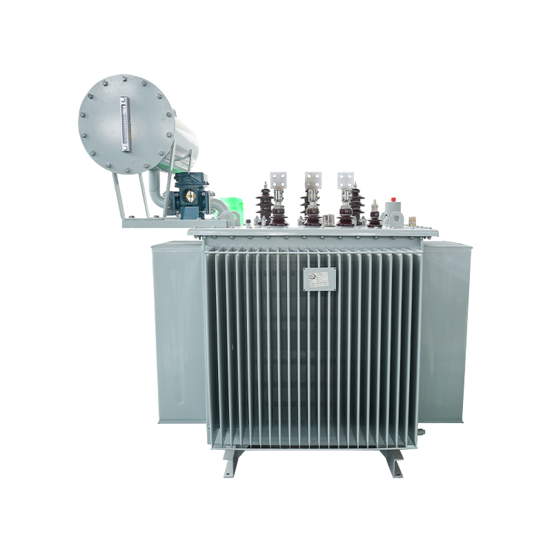
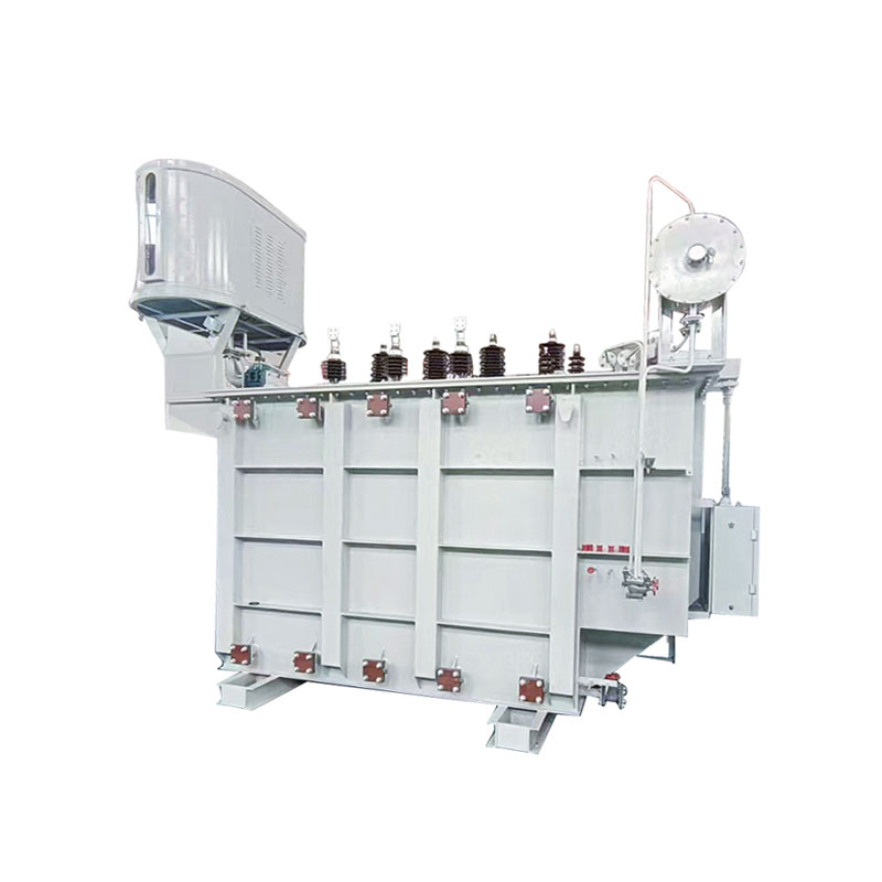 35kV Oil-Immersed Power Transformer 20000KVAOil-immersed transformer for 35kV indoor distribution and industrial use with smaller size, lower leakage, and better insulation; suits oil-filled discharge and dissolved gas analysis discussions.View Product →
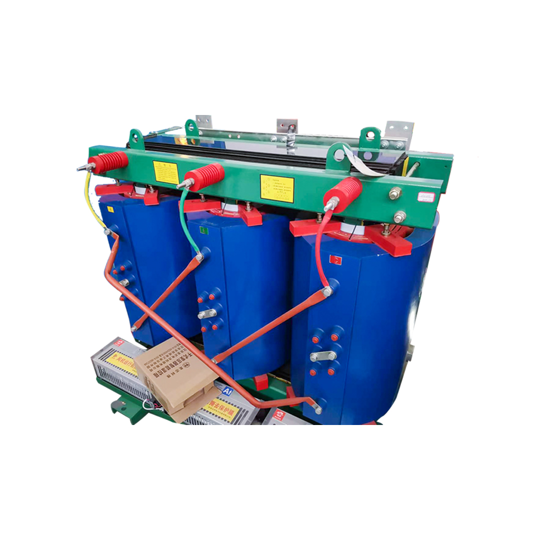
In cast-resin units, the usual culprits are voids trapped during casting, delamination between the resin and the conductor, and surface contamination that leads to tracking across the winding surface. Because there is no oil to carry by-products away, the discharge has to be caught electrically or acoustically. Cast-resin behaviour in this area is a topic in its own right, and we covered the practical side of it in our note on discharge, noise and insulation class in cast-resin transformers.
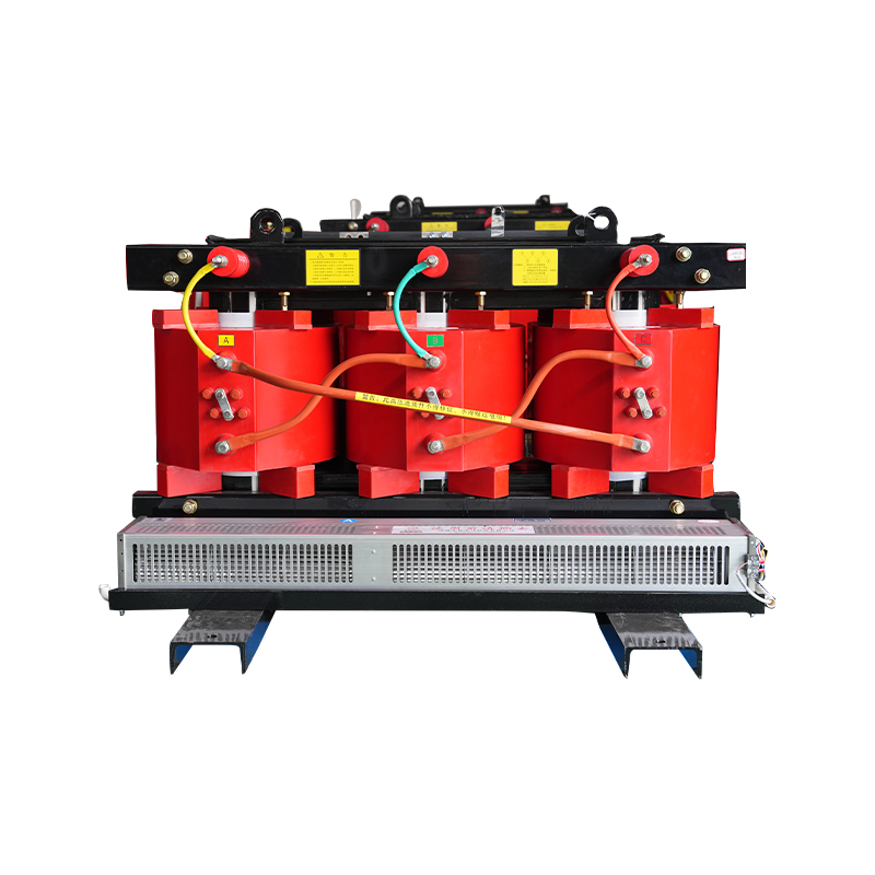
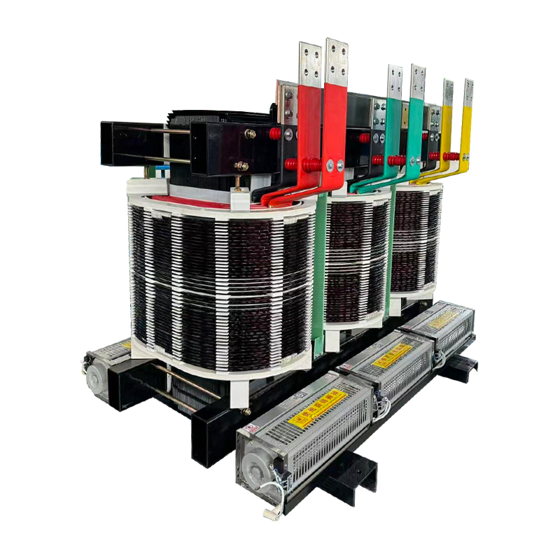
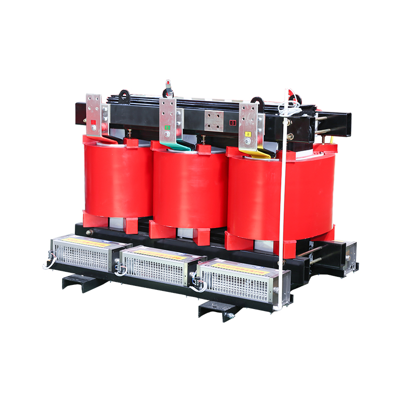 1000KVA 11KV Resin Cast Dry-Type TransformerCast-resin dry-type transformer for high-voltage connections using epoxy insulation for reliability and low maintenance; relevant to cast-resin discharge behavior and apparent charge interpretation.View Product →
A single apparent charge figure tells you very little on its own. What carries information is the combination of parameters:
For acceptance decisions, use the limit in the standard and the specification. For maintenance decisions, use the trend.
We are Jiangsu Dingxin Electric Co., Ltd., a transformer manufacturer based in the Haian Development Zone in Jiangsu, China. Our product range covers oil-immersed and dry-type transformers, amorphous alloy units, pad-mounted and prefabricated substations, phase-shifting rectifier transformers and switchgear, with power transformer lines extending to 110 kV and 220 kV and a stated annual production capacity of 50,000 MVA. We work to ISO 9001, ISO 14001, ISO 45001 and ISO 19011 management systems, and customers are welcome to visit the works and review test arrangements before an order is placed.
If your specification includes a discharge limit, tell us the standard, the voltage at which it is measured and the limit itself. We will confirm the test arrangement, include the readings in the routine test report, and explain anything that looks unusual before shipment rather than after.
You can reach our engineering team through the contact page with your voltage class, rating and test requirements.
It depends on the voltage class and the applicable standard. Limits commonly range from about 100 pC at 72.5 kV up to 200 pC or 300 pC at higher classes, always stated together with the measurement voltage. Your project specification is the final word.
Yes. On-line methods based on UHF sensors or acoustic detection can run continuously without an outage, but they give comparative and trending results rather than a calibrated pC value. Off-line measurements remain the reference method.
The principle is identical, but the likely defect sources differ. Cast-resin units are more prone to casting voids and surface tracking, and acoustic detection is often added because these defects couple well to structure-borne sound.
For a new unit, at commissioning. After that, the interval depends on criticality, age and history. A reasonable pattern for important assets is an initial survey, then a repeat after one year to establish a trend, then periodic surveys or continuous monitoring.
Partial discharge testing is not a magic pass or fail stamp. It is a measurement of a degradation process, and like any measurement it only earns its keep when the setup is calibrated, the conditions are recorded and the results are compared over time. Get those three things right and you will know more about your transformer insulation than any single test report can tell you.
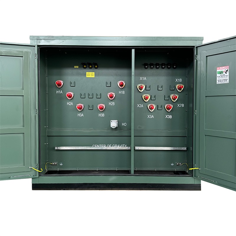
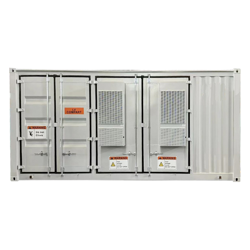
A Cabinet-Type Outdoor Prefabricated Substation, which is a compact, all-in-one electrical distribution solution designed for outdoor installation. Th...
See Details
Copyright © Jiangsu Dingxin Electric Co., Ltd. Rights Reserved.

Energy Efficient Transformers Manufacturers Electrical Transformers Factory
Contact Us