 English
 русский
 Español
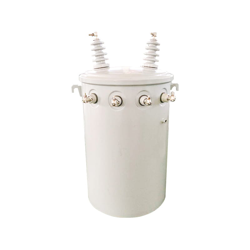

Amorphous Alloy Oil-Immersed Three-Phase Transformer
200KVA 10KV
See Details
Content
A 200 MW hydro plant can lose over 2% of its gross annual generation to transformer inefficiencies if the wrong unit is selected. Hydroelectric transformers sit at the nexus between turbine-generator output and the transmission grid—every megawatt-hour passes through their windings. Their job is threefold: step up the generator’s relatively low terminal voltage (commonly 11–20 kV) to transmission levels (132 kV, 220 kV, 400 kV or higher) to slash line losses over long distances, synchronize the plant’s output with grid frequency and phase, and provide galvanic isolation between the generator and the network to protect both sides from faults.
Long-distance AC transmission is unthinkable without a step-up transformer. Line losses are proportional to the square of the current; raising voltage from 11 kV to 220 kV reduces current by a factor of 20, which cuts resistive losses by a factor of 400. Beyond the electrical efficiency, transformers also enable multiple generating units to feed a common switchyard and allow the plant to black-start or island in emergency scenarios.
Engineers categorize hydroelectric transformers first by the role they perform inside the plant. Mixing up a generator step-up (GSU) unit with a station service transformer is not just a specification error—it can lead to catastrophic protection miscoordination. Three functional types dominate.
| Transformer Type | Primary Function | Typical Voltage Range | Share of Plant Capacity | Installation Location |
|---|---|---|---|---|
| Generator Step-Up (GSU) | Raises generator voltage to transmission level; handles full output of one or more units | LV: 11–20 kV, HV: 132–400+ kV | 90–100% of station capacity | Switchyard or powerhouse bay |
| Station Service (Auxiliary) | Steps down transmission voltage to supply plant loads (pumps, lighting, controls) | HV: 11–33 kV, LV: 0.4–0.69 kV | 5–10% of station capacity | Inside powerhouse, near MCC |
| Excitation | Feeds the generator’s field winding with controlled DC; provides isolation and voltage matching | LV: 0.4–3 kV, rectifier output DC | 0.5–1.5% of unit rating | Close to excitation cubicle |
The GSU transformer is by far the largest capital item and the unit most scrutinized during commissioning. Its impedance must be tuned to limit short-circuit contribution and to match the generator’s transient reactance. Station service transformers typically come from a tertiary winding of the GSU or from a separate feeder off the switchgear; in plants with multiple units, redundancy in station supply is a regulatory requirement. Excitation transformers, although small, must withstand heavy harmonic currents from thyristor rectifiers and high di/dt stress.
Voltage transformation direction alone is not a selection criterion—it is a consequence of a plant’s architecture. Still, the three modes address fundamentally different needs.
Confusing step-down with isolation can lead to safety gaps. Isolation transformers are built with reinforced insulation and electrostatic screens between primary and secondary, making them far more robust against common-mode transients than an ordinary step-down unit.
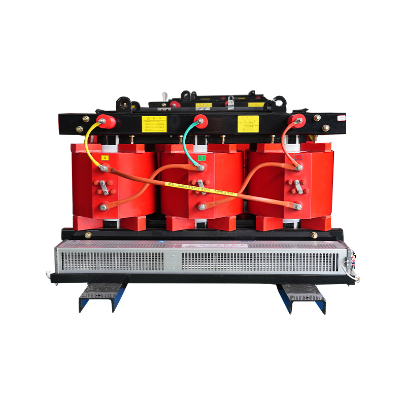
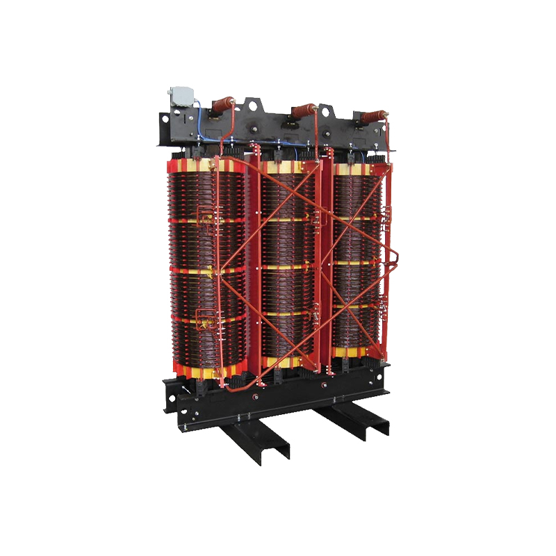
The choice between insulating oil and solid resin is arguably the most consequential decision for a hydro plant’s OPEX and fire safety posture. Oil-immersed transformers dominate the GSU role; dry-type transformers are gaining ground in station service and excitation applications where fire risk and maintenance access matter.
| Parameter | Oil-Immersed (ONAN/ONAF) | Dry-Type (Epoxy Cast Resin) |
|---|---|---|
| Maximum typical rating | 500 MVA and above | 40 MVA (limited by cooling capacity) |
| Cooling medium | Mineral oil / natural ester | Air natural, forced air, or solid resin |
| Installation environment | Outdoor, switchyard; requires oil containment | Indoor, or outdoor with enclosure; no oil pit needed |
| Fire risk | Moderate (flash point of mineral oil ~150 °C) | Very low (self-extinguishing resin) |
| Maintenance interval | Oil sampling/DGA every 6–12 months; bushing cleaning | Visual inspection annually; no oil handling |
| Initial CapEx (relative) | 100% baseline | 120–140% (for equivalent power) |
| 10-year TCO (including losses, maintenance, at $0.05/kWh) | Lower if load factor > 70%; total ownership cost advantage of 8–15% over dry-type | Competitive when load factor < 50% and fire safety premiums weigh heavily |
For a 50 MVA GSU transformer operating at 85% load factor, the difference in load loss between a typical oil-filled unit (99.6% efficiency) and a hypothetical dry-type unit of the same size (typically not available at this rating) would be dwarfed by the sheer unavailability of large dry-type GSUs. That is why in practice, hydro plants above a few MVA invariably use oil-immersed GSU transformers—the rating ceiling and proven outdoor robustness tip the scale decisively. Oil-immersed transformer designs offer industry-standard ratings optimized for high-voltage hydro applications. Station service and excitation transformers, however, increasingly employ dry-type technology. Our dry-type transformer lineup includes fully encapsulated windings that eliminate the risk of coolant leaks inside the powerhouse.
A methodical selection process eliminates guesswork and prevents costly mismatches. Plant engineers should mandate these five parameters in the technical specification.
These five parameters feed directly into a basic decision matrix: start with generator voltage and grid voltage to define the transformation ratio, then size for MVA capacity, then apply de-rating factors for temperature and altitude. When combined with the cooling method choice, the core specification is complete.
Standard GSU and service transformers cover the majority of installations, but several hydro niches demand specialty units that commercial off-the-shelf products cannot serve.
Hydroelectric transformers, especially GSU units, are long-life assets—30 years or more—if three failure mechanisms are managed proactively.
Scheduling maintenance during low-water season minimizes revenue loss. For a typical 150 MW station, a planned 2-week outage in the dry season can prevent an unplanned 6-week forced outage during the monsoon.
The transformer fleet is not a collection of static iron and oil tanks; it is the electrical backbone that defines a hydro plant’s availability and profitability. Start with a functional breakdown—GSU, station service, excitation—and apply the cooling-method choice only after the rating requirements are clear. Use the five key parameters to create a first-pass specification, then refine with total cost of ownership analysis that weighs CapEx against 10‑year loss and maintenance projections. Specialty transformers such as phase-shifting rectifiers or amorphous core units can unlock efficiency and reliability improvements that standard designs overlook. Above all, integrate a condition-based maintenance program rooted in regular DGA and PD monitoring. A transformer that fails prematurely can wipe out years of operational savings, but a well-chosen, well-maintained unit will quietly deliver power for decades.


Base kVA: 45 kVA to 12,000 kVA Primary voltage: 2400 V to 46,000 V Secondary voltage: 120 V to 24,940V Basic lmpulse Level (BIL): 30kV to 250kV
See DetailsCopyright © Jiangsu Dingxin Electric Co., Ltd. Rights Reserved.

Energy Efficient Transformers Manufacturers Electrical Transformers Factory


Contact Us