 English
 русский
 Español
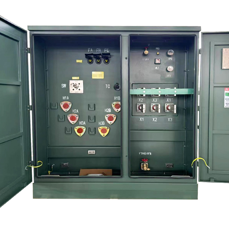
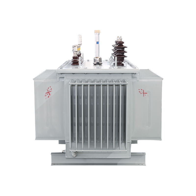
Energy-Saving Single-Phase Oil-Immersed Pole-Mounted Transformer
15KVA 13.8KV/0.4KV
See Details
Content
A 2,500 kVA substation in Abu Dhabi runs at 11 kV today. Tomorrow, it needs to deliver 6.6 kV for a different load profile. Rather than swapping out the entire unit, the engineering team flips a connection scheme—and the same transformer handles both voltage levels. That is the core promise of a dual voltage transformer: one unit, two output voltages, zero replacement downtime.
A dual voltage transformer carries two separate windings on its primary side, its secondary side, or both. By connecting those winding pairs in series or parallel, you change the effective voltage and current capacity without altering the transformer's kVA rating. The principle is straightforward: series connections add voltage while keeping current constant; parallel connections preserve voltage while doubling current capability.
This design shows up in a wide range of settings. Utility distribution networks use dual voltage primaries to accommodate legacy 4.16 kV and newer 13.8 kV feeds from the same pole-mounted unit. Solar inverter step-up stations switch between 480 V and 600 V outputs depending on grid interconnection requirements. Industrial motor control centers deploy dual voltage secondaries to power both 230 V and 460 V equipment from one transformer. Data center UPS systems rely on dual voltage configurations to serve mixed 208 V and 480 V rack power distribution simultaneously.
Understanding when and how to specify a dual voltage transformer—rather than a fixed-voltage model—can save capital expenditure, reduce spare inventory, and simplify site commissioning across multi-voltage facilities.
The behavior of a dual voltage transformer hinges entirely on how its paired windings are interconnected. Each winding has a nameplate voltage (Vw) and a rated current (Iw). Connecting them in series produces one set of output characteristics. Connecting them in parallel produces another. The kVA capacity remains constant in both cases—a fact that surprises many first-time specifiers.
In a series connection, the two winding voltages add together while the current stays at the single-winding rating. If each winding is rated 120 V at 10 A, the series output becomes 240 V at 10 A—still 2.4 kVA. In a parallel connection, the voltage stays at 120 V, but the current doubles to 20 A—again 2.4 kVA. The transformer does not gain or lose capacity. It simply trades voltage for current depending on how the terminals are strapped.
| Parameter | Series Connection | Parallel Connection |
|---|---|---|
| Output Voltage | 2 x Vwinding | Vwinding |
| Output Current | Iwinding | 2 x Iwinding |
| kVA Rating | Unchanged | Unchanged |
| Winding Utilization | Full voltage stress | Full current stress |
| Typical Application | High-voltage distribution | Low-voltage high-current loads |
What changes behind the scenes is the stress profile. Series operation places higher dielectric stress across the insulation system. Parallel operation drives higher current through the conductors, increasing I²R losses and thermal load. A well-designed dual voltage transformer accounts for both extremes—insulation clearances rated for the series voltage, conductor cross-sections sized for the parallel current. Cheaper designs often compromise on one dimension, which is why substandard units run hot in parallel mode or fail hipot tests in series mode.
For specifiers, the rule of thumb is direct: if your load needs voltage flexibility above all else, design for series operation and verify parallel capability as a secondary check. If your load demands high current at a fixed voltage, prioritize the parallel configuration in your thermal calculations.
Single-phase dual voltage transformers are the simplest entry point into this technology—and the most common in residential distribution, control circuits, and small commercial applications. They carry two primary windings (typically labeled H1-H2 and H3-H4) and two secondary windings (X1-X2 and X3-X4). The terminal labeling is not arbitrary; it encodes polarity information essential for correct wiring.
Polarity determines whether the voltages from two windings add or subtract when connected in series. If H1 and X1 are positioned on the same physical side of the core, the transformer exhibits subtractive polarity. If they sit on opposite sides, polarity is additive. This matters during commissioning: a voltmeter placed across the series-connected secondary will read either the sum or the difference of the two winding voltages, depending on which terminals are bridged. Getting it wrong can produce unexpected voltage levels or even short-circuit conditions.
A practical wiring sequence for a 120/240 V single-phase dual voltage secondary looks like this:
Single-phase units dominate pole-mounted distribution and small machine tool control panels. Their wiring logic is well-documented in ANSI C57.12.00 and IEC 60076-1, both of which mandate clear nameplate diagrams showing series and parallel terminal arrangements.
Scaling the dual voltage concept to three-phase systems introduces an additional layer of complexity: winding configuration. Each phase now carries split windings that can be connected in series or parallel, but the overall phase grouping—whether wye (star) or delta—interacts with those individual winding choices to determine line-to-line and line-to-neutral voltages.
Consider a transformer with two 277 V windings per phase. In a wye configuration with series-connected windings per phase, the phase voltage becomes 554 V and the line voltage reaches 960 V (554 x √3). With parallel windings in wye, the phase voltage stays at 277 V and line voltage at 480 V. If the same windings are arranged in delta, the line voltage equals the phase voltage directly—960 V in series delta, 480 V in parallel delta. The configuration choice between wye and delta can swing the available line voltage by a factor of up to 1.73, independent of the series/parallel decision.
| Phase Connection | Winding Mode | Phase Voltage | Line Voltage |
|---|---|---|---|
| Wye | Series | 554 V | 960 V |
| Wye | Parallel | 277 V | 480 V |
| Delta | Series | 960 V | 960 V |
| Delta | Parallel | 480 V | 480 V |
This flexibility is not merely academic. In photovoltaic step-up substations, a three-phase dual voltage transformer can serve a 480 V inverter today and a 600 V inverter tomorrow—no hardware change required. The site engineer simply re-straps the secondary terminals. For industrial variable-frequency drives using phase-shifting rectifier transformers, the dual winding structure enables 12-pulse or 24-pulse rectification schemes that slash harmonic distortion. Our phase-shifting rectifier transformers for medium and high voltage frequency converters leverage precisely this principle, using dual winding sets with controlled phase displacement to meet IEEE 519 harmonic limits without external filtering.
Specifiers should verify two things when evaluating three-phase dual voltage units: whether the manufacturer supports both wye and delta reconnection on the same core (some designs lock in one configuration), and whether the neutral terminal is adequately sized for unbalanced loading in wye-parallel mode.
Choosing a dual voltage transformer involves more than matching voltages. Engineering decisions ripple through thermal performance, lifetime reliability, and total cost of ownership. The following parameters form the minimum selection checklist for any serious evaluation.
Capacity (kVA) and Temperature Rise: Dual voltage transformers carry a nameplate kVA rating that applies to both series and parallel configurations. But the thermal behavior differs. A unit rated for 500 kVA with a 65°C average winding temperature rise can operate at 500 kVA continuously in either mode—provided ambient temperature stays within design limits. If the same unit carries a 55°C rise rating, it can deliver 12-15% more capacity in cooler environments. For outdoor installations in desert climates, specify 65°C rise with high-temperature insulation systems (Class H or better) to avoid premature aging.
Impedance Voltage (%IZ): Impedance shifts between series and parallel connections. Series mode typically yields higher impedance (better fault current limiting but poorer voltage regulation). Parallel mode reduces impedance, improving regulation at the cost of higher available fault current. A 5% IZ in series might drop to 3-4% in parallel—a detail that alters downstream breaker sizing.
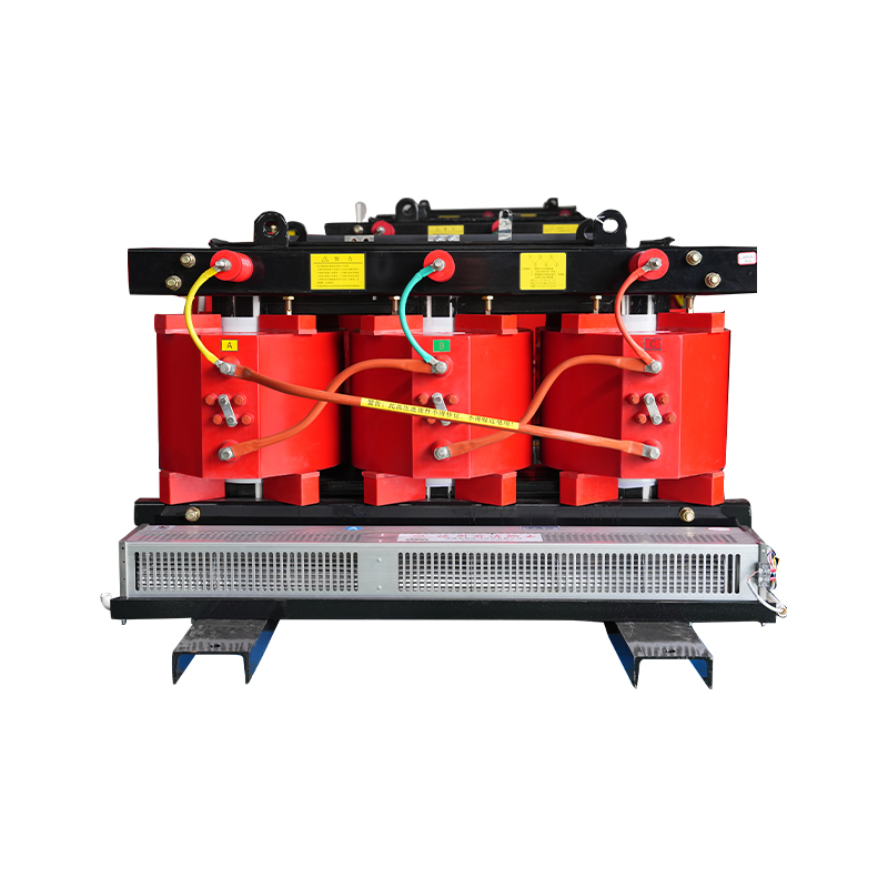
Insulation Type: Oil-immersed designs still dominate dual voltage applications above 500 kVA, especially for outdoor pad-mounted installations. A distribution transformer with dual voltage primaries fits neatly into utility grids undergoing voltage upgrades. For indoor or fire-sensitive environments, cast-resin dry-type dual voltage transformers eliminate oil containment requirements while handling voltages up to 35 kV.
Winding Material: Copper windings carry a 2-3% efficiency advantage over aluminum in parallel high-current mode, where I²R losses dominate. The cost premium for copper runs 20-30% on the purchase price but often pays back through reduced cooling load in data center applications.
Taps and Adjustment Range: Dual voltage capability should not be confused with tap-changing. Taps fine-tune voltage in small increments (±2.5%, ±5%). Dual voltage reconnection provides a wholesale voltage ratio change. Many industrial users combine both features: dual voltage windings for major voltage selection, plus ±2x2.5% taps for on-site trimming.
Dual voltage transformers are not theoretical curiosities. They are actively deployed across three growing sectors that reward infrastructure flexibility.
Solar PV Step-Up: Utility-scale solar farms use central inverters outputting at 480 V or 600 V AC, depending on the inverter manufacturer and local grid code. A dual voltage step-up transformer with a 480/600 V secondary and a 13.8 kV or 34.5 kV primary allows the EPC contractor to source one transformer type for multiple inverter brands. This simplifies procurement, cuts spare unit costs, and accelerates commissioning. In one recent 50 MW installation across two sites, the developer saved roughly 18% on transformer procurement by standardizing on a single 2.5 MVA dual voltage design rather than ordering separate 480 V and 600 V inventory.
Industrial VFD and Motor Control: Many process plants operate mixed-voltage motor fleets—230 V for auxiliary pumps, 460 V for main drives. A single dual voltage secondary transformer can feed both voltage levels through separate switchgear buses, eliminating the need for a second transformer. For 12-pulse and 18-pulse drive front-ends, dual secondary windings with phase displacement suppress 5th and 7th harmonic currents. The transformer effectively becomes a built-in harmonic filter, helping facilities meet IEEE 519 without external capacitor banks or active filters.
Data Center Power Distribution: Hyperscale data centers increasingly adopt 480 V distribution for rack-level power shelves while maintaining 208 V legacy circuits for lighting and ancillary loads. A single dual voltage PDU transformer eliminates redundant units, saving floor space and reducing fault points. Dry-type transformers dominate this segment due to fire safety requirements and the need for units that can operate inside the white space without oil containment.
Dual voltage capability is not free. It demands additional winding taps, heavier terminal blocks, and more complex insulation coordination. The bill of materials grows, and so does the transformer's physical footprint. Quantifying these trade-offs helps engineers decide when the premium makes sense.
| Criterion | Fixed Voltage Transformer | Dual Voltage Transformer |
|---|---|---|
| Purchase Cost | Baseline | +15% to +25% |
| Efficiency (full load) | 98.5–99.2% | 98.2–98.9% (-0.1 to 0.3%) |
| No-Load Loss (series mode) | Baseline | ~40% lower (halved flux density) |
| Load Loss (parallel mode) | Baseline | Up to 4x on winding conductors |
| Footprint | Baseline | +10% to +20% |
| Voltage Flexibility | Fixed ratio only | Two ratios via re-strapping |
| Spare Unit Inventory | One per voltage class | One unit covers two voltages |
The efficiency story is more nuanced than a single percentage point suggests. In series mode, the core flux density is effectively halved because the full voltage is shared across twice the turns. This reduces no-load (iron) losses by roughly 40% compared to an equivalent fixed-voltage design. The downside appears in parallel mode, where each winding carries full rated current and the conductor cross-section may be undersized for the combined current—leading to higher I²R losses. However, well-designed units compensate with larger conductors, mitigating the penalty to 1-2% additional load loss.
For applications that switch voltage modes infrequently—say, during a one-time grid upgrade—the lifetime cost argument favors dual voltage. For applications that toggle between voltages daily under varying loads, the parallel-mode efficiency penalty compounds and may tip the balance toward two separate fixed-voltage units.
Specifying a dual voltage transformer for a custom application requires clear communication of operating conditions. Manufacturers need a complete parameter set to quote accurately and deliver a unit that performs reliably across both voltage modes.
Prepare the following data before reaching out to a supplier:
A complete inquiry reduces back-and-forth by days. It also signals to the manufacturer that you have done the engineering groundwork, which tends to yield more technically responsive proposals rather than generic cut-sheet resends. If your application spans solar, industrial drive, or data center environments, mention the specific operating profile—intermittent vs continuous duty directly affects thermal design margins.


Copyright © Jiangsu Dingxin Electric Co., Ltd. Rights Reserved.

Energy Efficient Transformers Manufacturers Electrical Transformers Factory


Contact Us