 English
 русский
 Español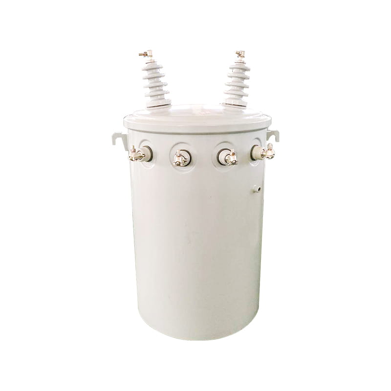
Energy-Saving Single-Phase Oil-Immersed Pole-Mounted Transformer
15KVA 13.8KV/0.4KV
See Details
Content
A 110 kV substation took 16 months from concept to energization because the team skipped load-flow studies in the early phase. That single oversight cascaded into three major equipment changes and a $1.2 million budget overrun. Substation design succeeds only when you follow a rigid phased methodology. Each phase produces specific deliverables that validate the next set of decisions.
The six-phase process starts with feasibility and site selection. Engineers gather load forecasts, environmental constraints, and grid interconnection requirements. The output is a preliminary single-line diagram and a conceptual layout. Phase two runs deep system studies: short-circuit analysis, load flow, and transient stability. These studies yield the short-circuit current levels, voltage profiles, and breaker duty requirements that drive all equipment ratings.
Phase three selects primary equipment—transformers, switchgear, busbars, and reactors. Every specification ties back to the system study numbers. Phase four finalizes the physical layout, civil works, and grounding grid. Phase five designs the protection, control, and SCADA architecture. Phase six encompasses construction, testing, and commissioning. Each handoff between phases should include a formal design review checklist.
A common failure pattern is conducting system studies after equipment is already ordered. That forces compromises in protection coordination and can leave transformers vulnerable to through-fault damage. Follow the sequence. Let the numbers drive the hardware choices.
You cannot size a circuit breaker or set a relay pickup without knowing the maximum available fault current. System studies are not optional paperwork. They are the analytical backbone of every technical specification. The three foundational studies are short-circuit analysis, load-flow analysis, and protection coordination.
Short-circuit analysis calculates three-phase and line-to-ground fault currents at each bus. For a typical 110 kV substation with a 2,500 MVA upstream grid, the three-phase symmetrical fault level often sits between 20 kA and 40 kA. The single-phase-to-ground fault can exceed 30 kA if the neutral is solidly grounded. These numbers determine the interrupting rating of circuit breakers, the short-time withstand of busbars, and the thermal limits of current transformers.
Load-flow analysis confirms voltage profiles and equipment loading under peak and minimum generation scenarios. Engineers check that transformer tap changers can maintain secondary voltage within 0.95–1.05 pu. They also identify overloaded lines and reactive power deficits. Protection coordination then builds on both studies. Using time-current curves (TCCs), designers set relay time dials and pickup currents so that a fault on a feeder clears before the transformer backup protection operates. Coordination intervals of 0.2–0.3 seconds between series devices are standard practice.
The table below shows typical short-circuit levels for common substation voltages, assuming a strong grid contribution.
| Voltage Level (kV) | Fault Level Range (kA) | Typical Breaker Rating (kA) |
|---|---|---|
| 35 | 16 – 31.5 | 25 or 31.5 |
| 110 | 20 – 50 | 40 or 50 |
| 220 | 31.5 – 63 | 50 or 63 |
Run these studies with software like ETAP, DIgSILENT PowerFactory, or PSS/E. Always model the worst-case grid configuration—maximum generation and all lines in service.
Equipment selection is where capital cost, lifetime operation, and site constraints collide. Get it wrong, and you will pay for it twice—once in the purchase order and once in the maintenance budget. The three largest decisions are transformer type, switchgear insulation medium, and busbar configuration.
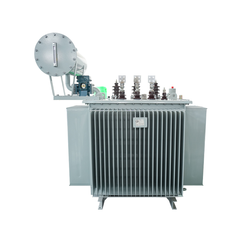
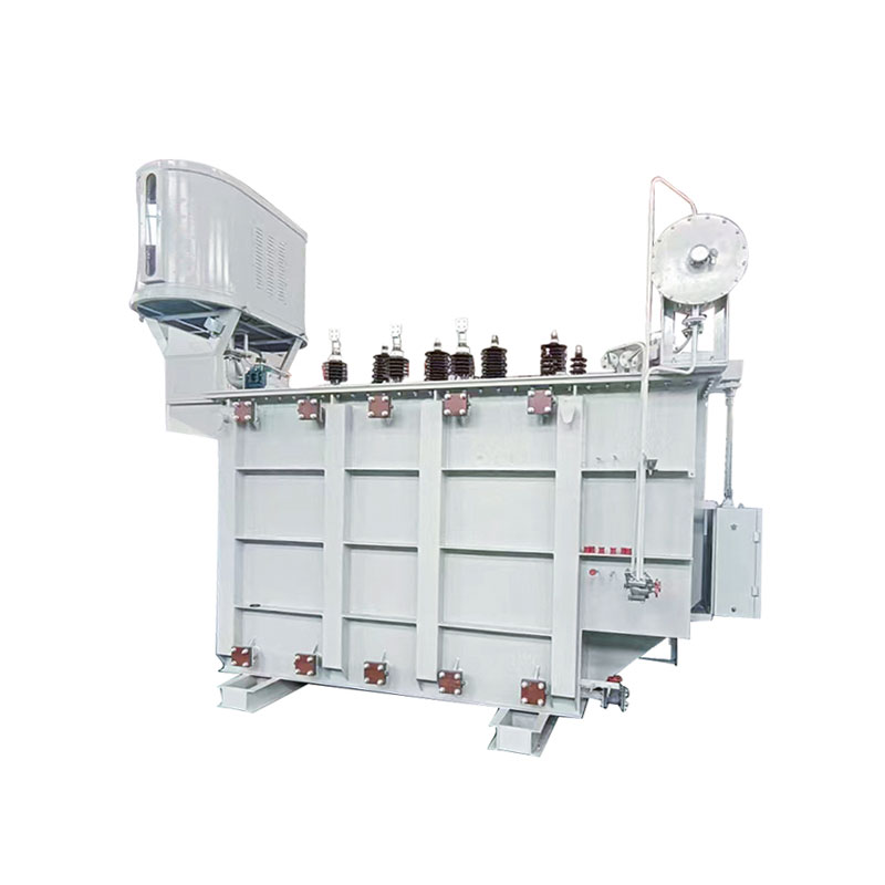
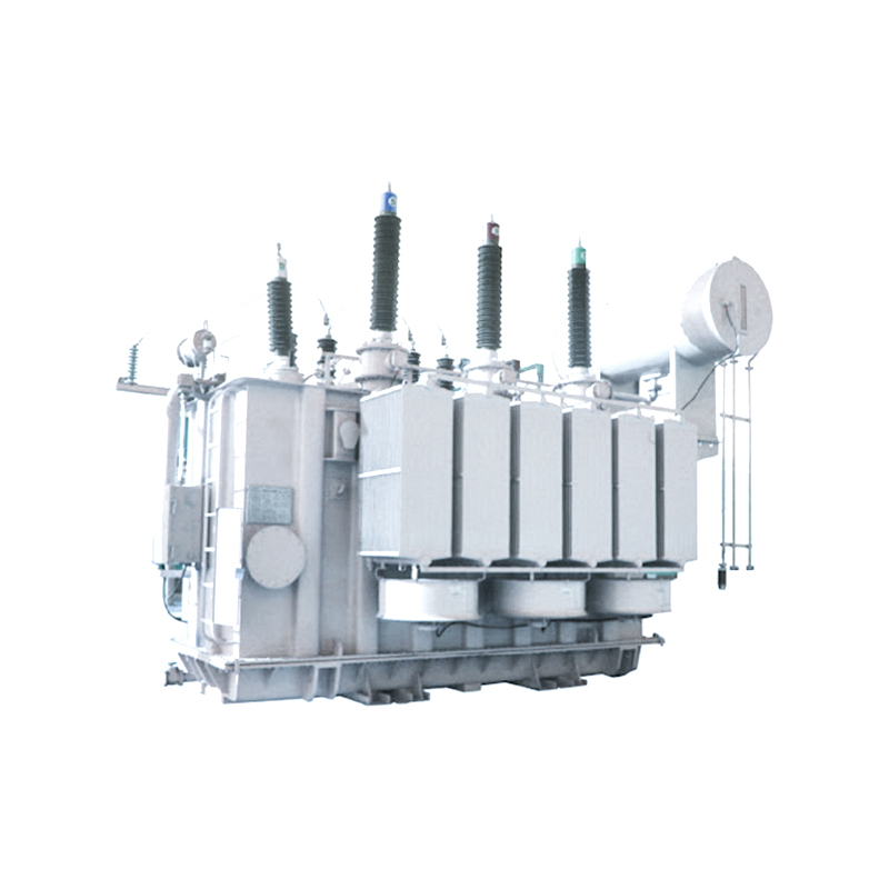
Oil-immersed transformers dominate substations above 35 kV because of their superior cooling and higher BIL ratings. A typical 110 kV / 20 kV, 50 MVA unit uses mineral oil with forced oil and forced air cooling. Full-load losses for such a unit range from 150 kW to 200 kW. Oil-immersed transformers offer lower first cost per MVA and better overload capability, but they require fire suppression systems and oil containment pits when installed indoors or near buildings.
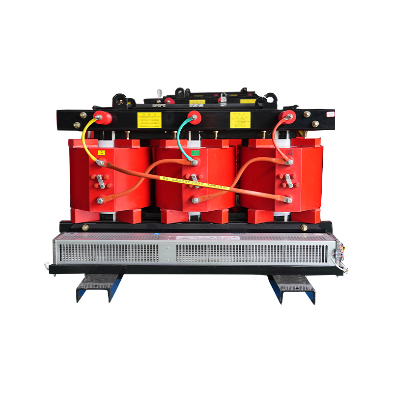
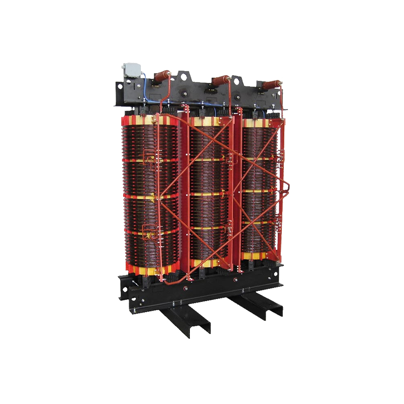
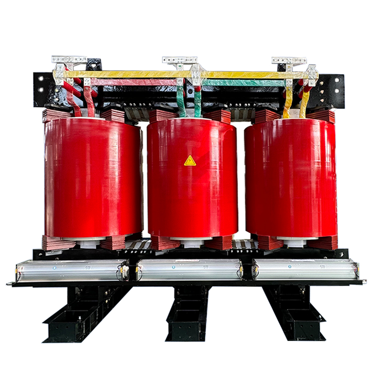
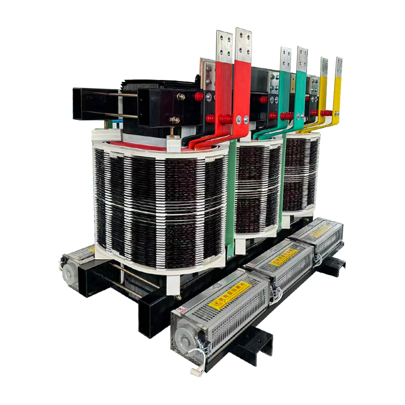
Dry-type transformers, especially epoxy-resin cast-coil designs, excel in urban substations, underground vaults, and locations with strict fire codes. A 35 kV / 0.4 kV, 2.5 MVA cast-resin unit dissipates heat through natural air convection, eliminating oil pumps and radiators. The penalty is a higher initial cost—roughly 20–30% more than an equivalent oil-filled unit—and a larger footprint for the same kVA. The table below compares the two technologies across six decision factors.
| Criterion | Oil-Immersed | Dry-Type (Cast Resin) |
|---|---|---|
| Upfront cost per MVA | Lower | 20–30% higher |
| Fire risk | Requires suppression system | Self-extinguishing |
| Maintenance interval | 6–12 months (oil sampling) | 12–24 months (visual/cleaning) |
| Overload capacity | 150% for 30 min (typical) | 130% for 30 min |
| Noise level | 65–75 dB(A) | 60–70 dB(A) |
| Outdoor installation | Standard | Requires enclosure (IP4X or better) |
Air-insulated switchgear (AIS) uses atmospheric air as the insulating medium. It is the default choice for outdoor 35–220 kV substations with ample space. A single 110 kV AIS bay occupies roughly 8 m × 12 m. Gas-insulated switchgear (GIS), by contrast, encloses all live parts in sealed tubes filled with SF6. The same 110 kV bay shrinks to about 2 m × 6 m. GIS is mandatory for urban indoor substations and coastal sites where salt pollution would degrade AIS insulators within two years.
GIS costs 2–3 times more than AIS for the same ratings. But when land costs exceed $500 per square meter, the smaller footprint often flips the total installed cost in GIS’s favor. Maintenance of GIS is lower for the primary contacts, though gas monitoring and leak detection add a specialized cost layer.
Single-bus layouts are cheapest but require a full station outage for maintenance. Double-bus or breaker-and-a-half schemes deliver operational flexibility. For a 220 kV substation with six feeders, a breaker-and-a-half configuration adds about 30% to the switchgear capital cost but eliminates complete station outages during breaker maintenance. Choose the bus scheme based on the utility’s N-1 reliability criterion.
Physical layout and grounding are inseparable. The placement of equipment determines the fault current path length, which directly affects step and touch voltages. A well-designed layout also simplifies cable trenches, reduces earthwork, and speeds up construction.
Start with the single-line diagram and assign physical bays. Position the transformer bay adjacent to the switchgear building to minimize bus duct length. For outdoor air-insulated stations, maintain minimum phase-to-phase and phase-to-ground clearances per IEC 61936-1. At 110 kV, the standard phase-to-phase clearance is 1,300 mm and phase-to-ground is 1,100 mm. For 220 kV, these figures rise to 2,100 mm and 1,800 mm respectively.
Grounding design aims for a total ground resistance of 1 ohm or less for large substations and 5 ohms for small distribution stations. The grid typically consists of bare copper conductors buried 0.5–0.7 m deep, forming a mesh with 4–6 meter spacing. Where soil resistivity exceeds 500 ohm-m, you must deploy vertical ground rods or chemical treatment. Calculate touch and step voltages under worst-case grid current. The allowable touch voltage for a 0.5-second clearing time on crushed rock surfacing is around 660 V. If the computed touch voltage exceeds this, tighten the grid spacing or add surface insulation.
Lightning protection uses the rolling sphere method. For a protection level II substation, the sphere radius is 30 m. Position shield wires or lightning masts so that all energized equipment lies within the zone of protection. A 20 m tall mast provides a lateral protection distance of approximately 24 m at a 12 m equipment height.
Protection must be fast, selective, and dependable. The primary protection for a power transformer above 10 MVA is usually a current differential relay with harmonic restraint. This relay detects internal faults by comparing currents entering and leaving each winding. For a 110/20 kV, 50 MVA transformer, typical differential pickup is set at 0.2–0.3 per unit with a slope of 30–40% to avoid tripping on CT saturation during external faults.
Backup protection includes time-overcurrent elements on the high-voltage and low-voltage sides. Phase overcurrent pickup is set at 125–150% of the transformer’s full-load current; ground overcurrent pickup is often set at 20–30% of the full-load current for sensitively grounded systems. Breaker failure protection initiates a trip of all adjacent breakers if the primary breaker does not clear the fault within 150–200 ms.
The control system architecture now universally adopts IEC 61850 for substation automation. Digital relays, merging units, and bay controllers communicate over a station bus using GOOSE messages for interlocking and MMS for SCADA interfaces. IEC 61850 reduces copper wiring by 60–80% compared to hardwired schemes. When the utility operates a legacy SCADA interface, a protocol gateway converts DNP3 or Modbus to the station bus. Always specify that protective relay settings shall be stored in a non-volatile format and that all event records are time-synchronized via an SNTP or IRIG-B master clock.
A solar farm substation is not a scaled-down version of a utility switching station. It must handle high harmonic content, bidirectional power flow, and the risk of unintentional islanding. Ignore these factors, and you will face relay misoperations and inverter tripping.
Harmonic distortion from inverters typically concentrates at low-order frequencies—5th, 7th, 11th, and 13th. The total harmonic distortion (THD) at the point of interconnection should stay below 5% per IEEE 519. When THD exceeds this limit, engineers add passive tuned filters or active harmonic filters. A passive filter tuned to the 5th harmonic with a quality factor of 20 can reduce that harmonic current by 80%. Active filters, while more expensive, adapt to changing inverter operating points.
Islanding detection requires a combination of passive methods (under/over voltage, under/over frequency) and active methods (frequency shift, reactive power export variation). The anti-islanding relay must disconnect the plant within 2 seconds of grid loss. Transformer selection also demands attention. A dedicated inverter-duty transformer must withstand the additional winding stress from harmonic currents. Phase-shifting transformers can be employed to create multi-pulse rectifier configurations that cancel specific harmonic orders before they reach the grid, reducing filter cost and footprint.
For wind farms, voltage flicker and low-voltage ride-through (LVRT) capability drive the substation design. The transformer impedance typically sits between 8% and 12% to limit voltage dip during turbine start-up. Ensure the LVRT curve of the wind turbines matches the grid code requirements—remaining connected for a zero-voltage condition for 150 ms is a common mandate.
A transformer built to IEC 60076 will not necessarily meet IEEE C57.12.00 requirements without design adjustments. The differences appear in temperature rise limits, insulation levels, and noise testing conditions. Export projects that fail to reconcile these standards at the specification stage inevitably face expensive rework.
The table below highlights three critical divergence points.
| Parameter | IEC 60076 | IEEE C57.12.00 |
|---|---|---|
| Top-oil temperature rise (55°C ambient) | 65 K | 65 K (but with different loading assumptions) |
| Winding temperature rise | 65 K (average) | 65 K (hottest-spot 80 K rise often used) |
| BIL for 110 kV winding (kV peak) | 450 | 450 (with some variants at 550) |
| Noise test method | Sound power level (dB) | Sound pressure level at 0.3 m (dB) — not directly comparable |
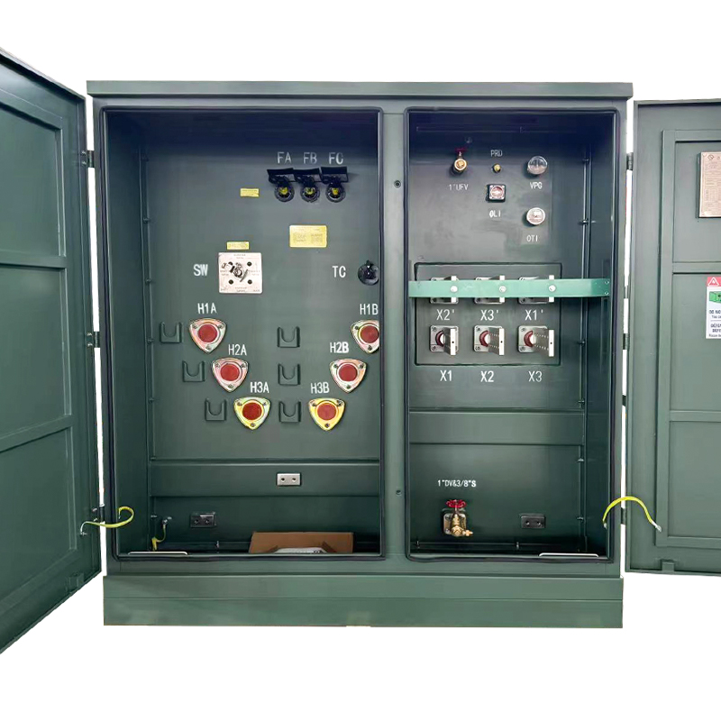
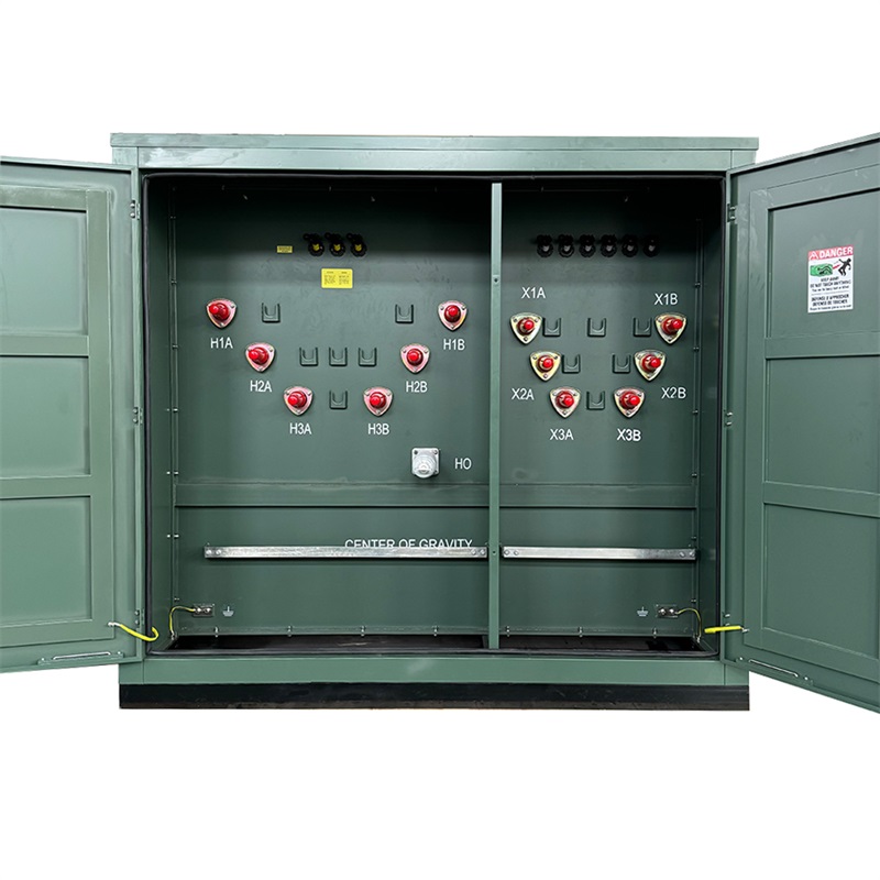
For switchgear, IEC 62271-1 defines rated voltage and current differently than IEEE C37. When specifying equipment, state the applicable standard explicitly and demand a compliance certificate. Manufacturers capable of delivering dual-certified products eliminate alignment risks. A European-style pad-mounted transformer, for instance, can be engineered to satisfy both IEC and IEEE insulation coordination requirements with minor modifications to bushing creepage distance.
Budget realism separates approved projects from shelved proposals. A 110 kV greenfield outdoor AIS substation with two 50 MVA transformers and six feeder bays typically costs between $4 million and $7 million in equipment and construction. The transformer package alone consumes 30–35% of that total. Switchgear accounts for 20–25%, while civil works and foundations add another 15–20%. The remaining amount covers protection, control, SCADA, and commissioning.
Timelines follow a predictable pattern. The design and procurement phase for a 110 kV station takes 5–7 months. Civil construction and equipment installation take 6–8 months. Commissioning and grid synchronization span an additional 2–3 months. The whole program, from signed contract to commercial operation, occupies 12–18 months. A 220 kV GIS station with more bays and higher voltage ratings adds roughly 4–6 months to both design and installation phases.
Cost overruns most often originate from three sources: late changes in grid interconnection requirements, unforeseen ground conditions that demand deep piling, and extended factory acceptance testing (FAT) schedules due to specification mismatches. Allocate a 10–15% contingency on the equipment budget and fix the interconnection agreement terms before issuing major purchase orders.

Copyright © Jiangsu Dingxin Electric Co., Ltd. Rights Reserved.

Energy Efficient Transformers Manufacturers Electrical Transformers Factory
Contact Us