 English
 русский
 Español
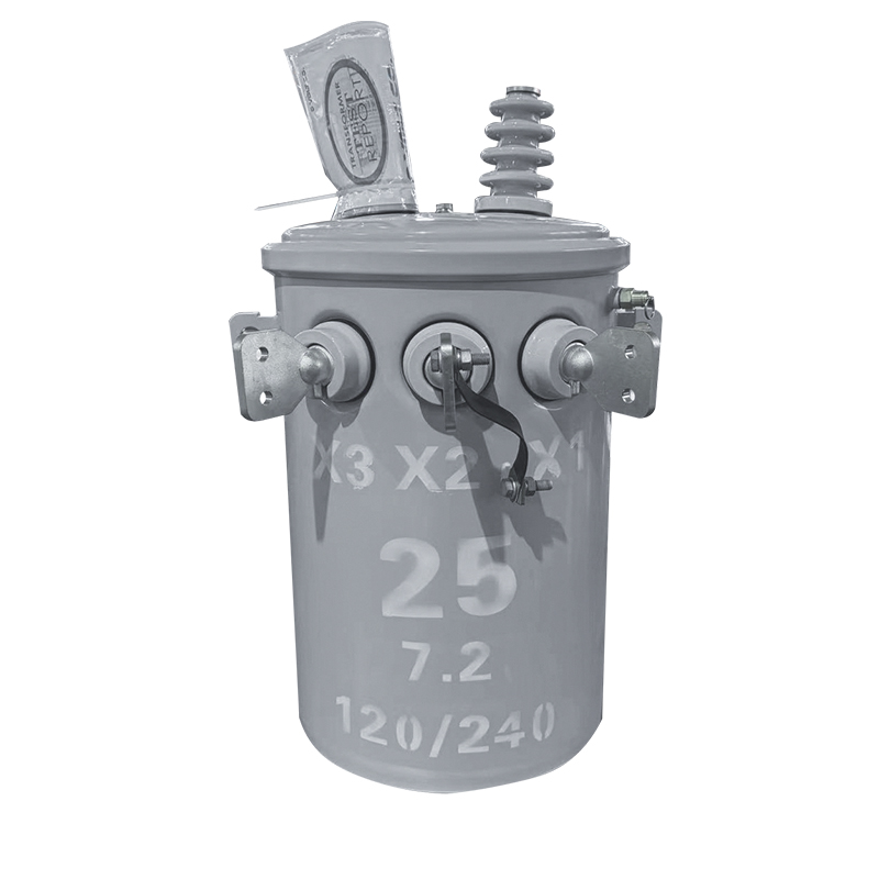
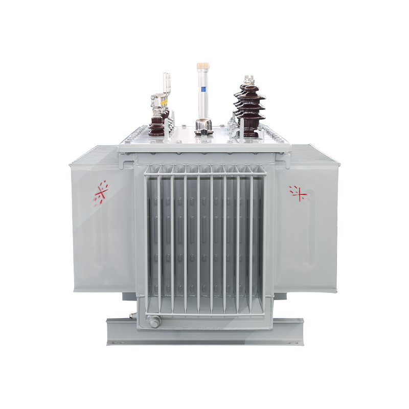
50KVA Single-Phase Pole-Mounted Oil-Immersed Transformer
50KVA 34.5KV/0.48KV
See Details
Content
A 250 kW compressor starts across the line, the workshop lights dip for a second, and a contactor two panels away chatters open. Nothing in the circuit has failed; the transformer upstream simply let its secondary voltage sag while the motor drew several times its rated current. That sag is exactly what the voltage regulation figure on a datasheet is meant to predict, and it remains one of the most practical - and most often misread - numbers in transformer purchasing. The short version: voltage regulation states how far a transformer's secondary voltage falls between no-load and rated load, a lower percentage means a stiffer output, the value itself is fixed by winding resistance, leakage reactance and impedance, and tap changers absorb the drift that regulation alone cannot. The rest of this article explains where the number comes from, what moves it, and which line items deserve scrutiny before an order is signed.
Voltage regulation is conventionally expressed as: VR (%) = (V no-load - V full-load) / V full-load x 100. Worked example: a 1,000 kVA unit converting 11 kV to 400 V reads 420 V at its secondary terminals with the load disconnected and 404 V at rated output. The regulation is (420 - 404) / 404, or about 4%. One caution on conventions: most textbooks and test reports use the full-load voltage as the base, but some references divide by the no-load value instead. Figures are only comparable when the same base is used, so it is worth confirming which convention a supplier applies before ranking two offers.
Full-load regulation is also almost never measured directly in a test hall, since loading a large unit to rated kVA during a routine test is impractical. It is derived from measured impedance and load losses, which is why the routine test report, not the brochure, is the real source of truth.
The percentage only means something against the statutory band the output must respect. European practice (EN 50160) allows roughly ±10% at the supply terminals, while North American ANSI C84.1 Range A expects service voltage within about ±5%. A transformer with weak regulation eats into that budget before cabling and the load itself contribute their own drops.
Load current flowing through copper produces an I²R drop that sits in phase with the current, and it is the dominant term at unity power factor. The same loss appears on the test report as load loss, or copper loss. Resistance also rises with heat - roughly 0.4% per degree Celsius for copper - so a transformer that has carried load since morning regulates slightly worse than a cold one. Guarantees are therefore quoted at a fixed reference winding temperature, typically 75 °C for oil-immersed designs.
Not all flux created by one winding links the other. The leakage portion behaves as series reactance, and its voltage drop leads the current by 90 degrees. Reactance is usually far larger than resistance: a distribution transformer with 4.5% impedance may hold only around 1% of that as resistance, so reactance dominates the regulation figure whenever load current lags.
With a lagging load - motors, welders, most industrial plant - the reactive and resistive drops add together, and regulation worsens sharply. A unit that holds about 1% at unity power factor can show 3.5% to 4% at 0.8 lagging. With a capacitive, leading load the arithmetic reverses: secondary voltage can rise as load grows, producing negative regulation. Plants with large power-factor-correction banks should check this case explicitly, because the failure mode flips from brownout to overvoltage trips.
Impedance combines resistance and reactance into the single number buyers see first. Low impedance holds the voltage up but lets fault current climb and multiplies the mechanical forces a winding must survive during a short circuit. High impedance does the opposite, at the cost of a deeper dip every time a large motor starts. Standards leave room for both answers: IEC 60076 practice puts distribution-class units near 4-6%, while 110 kV and 220 kV network transformers typically sit between 10% and 14%. Neither value is better in the abstract; they answer different questions.
| Transformer class | Typical short-circuit impedance | Approx. regulation at rated load, 0.8 PF lagging | Usual voltage-control method |
|---|---|---|---|
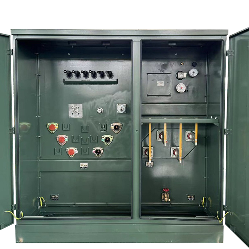
| Pole- and pad-mounted distribution units up to about 2.5 MVA | 4-6% | 3-5% | Off-circuit taps, ±2 x 2.5% |
| 35 kV industrial power transformers | 6.5-8% | 4-6% | Off-circuit or on-load taps |
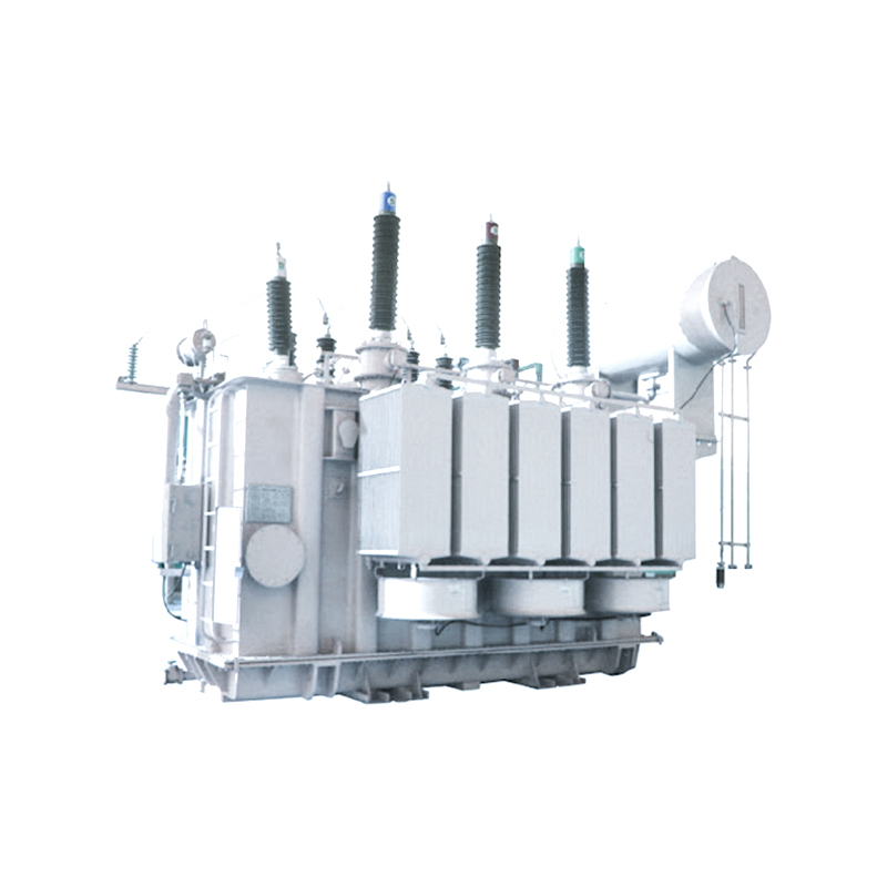
| 110-220 kV network power transformers | 10-14% | 7-9% | On-load tap changer, e.g. ±8 x 1.25% |
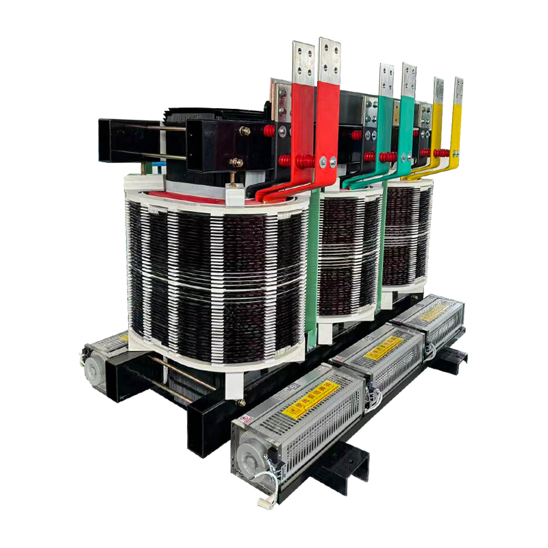
| Cast-resin dry-type, 10 kV class | 4-6% | 3.5-4.5% | Off-circuit taps |
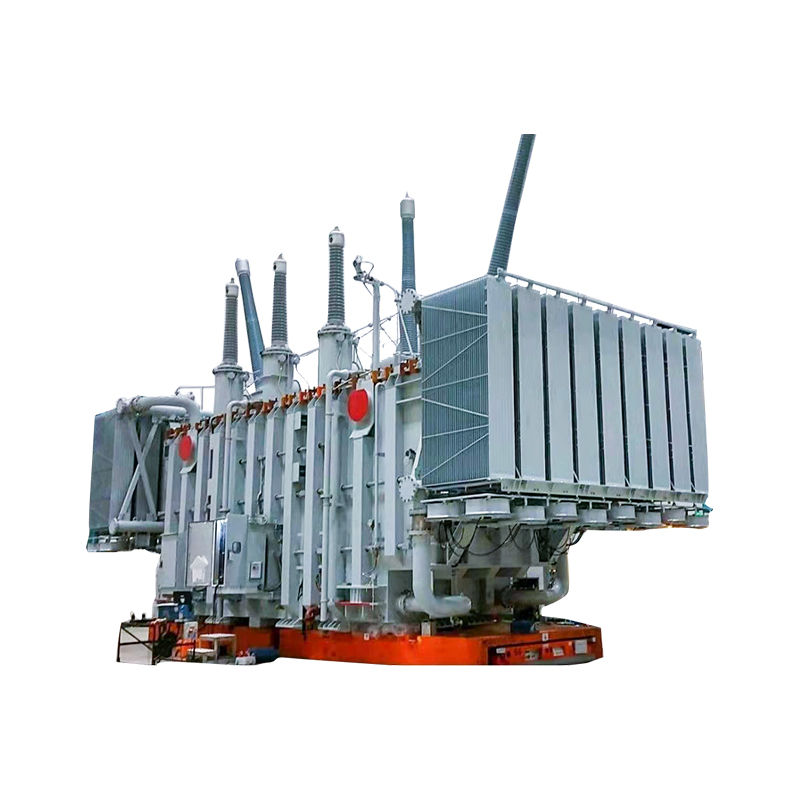
Small oil-immersed distribution transformers get tight regulation almost for free, because the low impedance a feeder wants is exactly what improves their figure. Large network units take the opposite bargain: impedance climbs with voltage class to limit fault duty, natural regulation weakens toward 7-9%, and an on-load tap changer recovers the control. That is standard practice on 110 kV and 220 kV power transformers, and it should be treated as a core design decision rather than an accessory bolted on afterward.
Regulation is a fixed property of the winding geometry; a tap changer works on the ratio instead. Two families cover most needs.
Off-circuit taps - usually ±2 x 2.5% on distribution units - are moved only with the transformer de-energized, typically once at commissioning to center the output on the local grid's real behavior. They are inexpensive and entirely adequate where the supply voltage stays put.
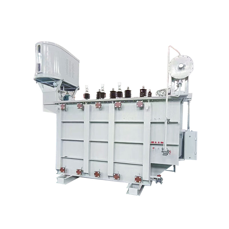
On-load tap changers shift ratio while the unit carries full load, tracking daily load swings and upstream variation. Ranges near ±10% in steps of 1.25% are common on transmission-class equipment, and IEC 60214 governs their design and testing. Because the mechanism is electromechanical and wears with every operation, contact maintenance is scheduled by operation count rather than calendar alone; the working principle and upkeep of load tap changers (LTCs) merit their own reading before a buyer fixes a range and step size.
The selection logic is simple enough to state. Stable supply with a stable load means off-circuit taps are enough. A grid that swings, or a load that cycles hard every day, justifies the premium of on-load regulation.
Datasheet comparisons fall apart when the conditions behind each number differ. Five checks keep the comparison honest:
One observation from the manufacturing side is worth adding: two offers can quote an identical 4% impedance and still regulate differently, because the split between resistance and reactance - the R/X ratio - depends on conductor choice, winding arrangement and cooling. The load-loss and resistance lines of the test report expose that split, which is why they belong in the comparison alongside the impedance headline.
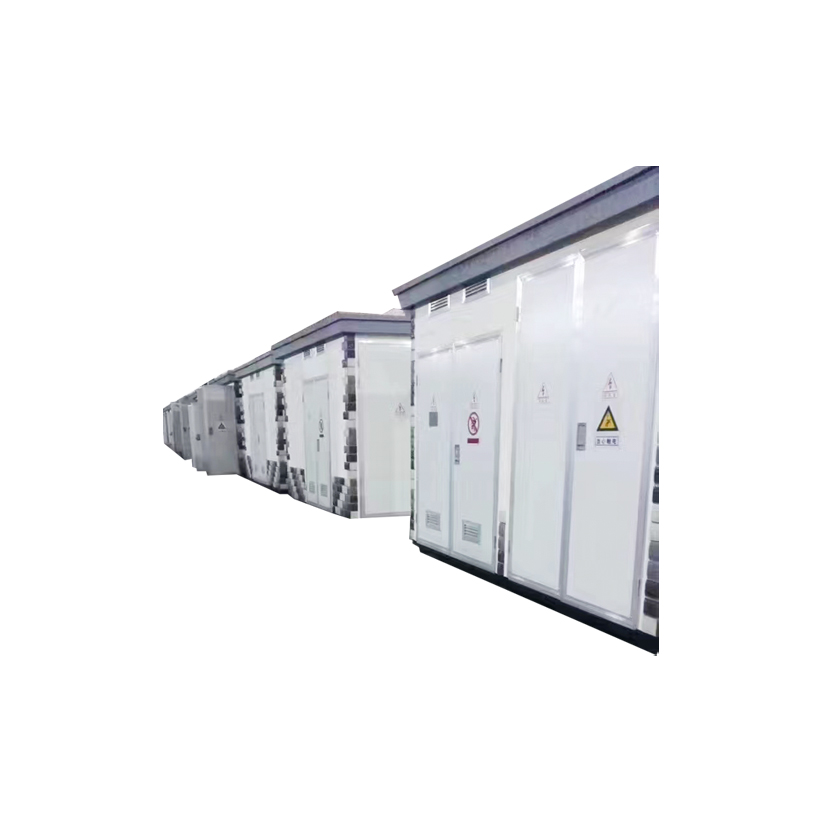
Treat voltage regulation as a system question rather than a single percentage: the impedance the network can tolerate, the power factor the load actually presents, the taps that absorb the drift, and the test data that proves all three. Buyers who tie those threads together get equipment whose output behaves on the plant floor the way the datasheet promised. Outdoor feeders are usually served by the oil-immersed families discussed above, while indoor and fire-sensitive sites often solve the same equation with cast-resin dry-type transformers, whose guarantees are referenced to the winding temperature of their insulation class - the same scrutiny applies to both.

Copyright © Jiangsu Dingxin Electric Co., Ltd. Rights Reserved.

Energy Efficient Transformers Manufacturers Electrical Transformers Factory
Contact Us